Bob,
Brought all of my units and my CT clamps from you - up until recently no issues at all
Noticed that my main unit that monitors my solar, battery, total consumption and Grid was reporting essentially a flat output on one of its CTs
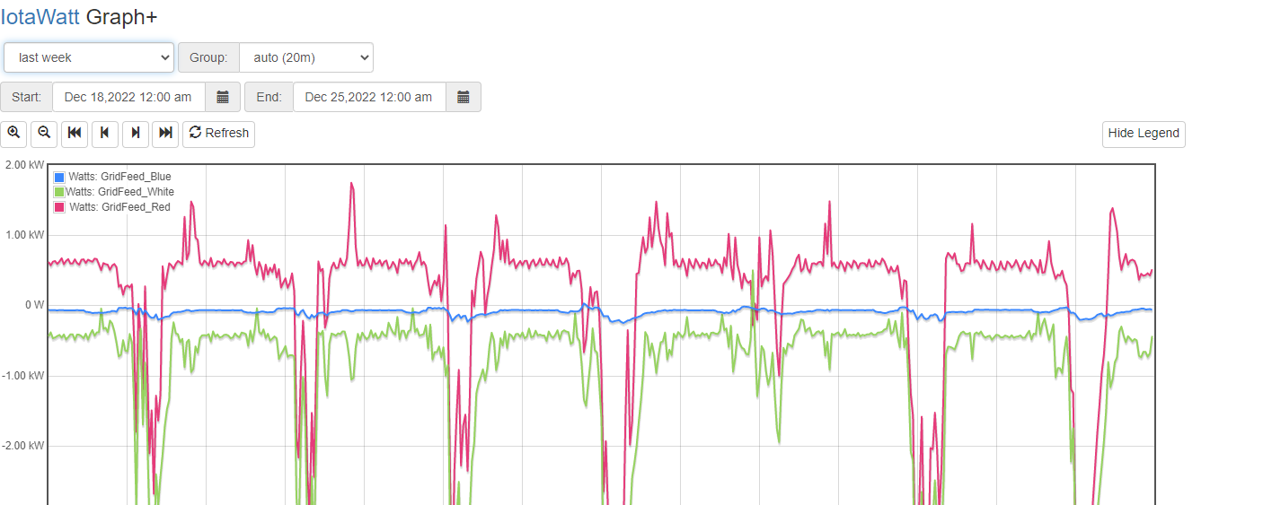
As per below - this is for the last week
You will note the flat blue line
Right now for example we are making 10KW of solar, and consuming about 4KW - so i should have 6KW going out to the grid (battery was full earlier this morning)
I just happened to notice that the Blue export to grid was much lower than the other phases - i checked the voltage of the phases via the solar inverters (i have two of them) and they are not high (around 247v) per phase.
I then started running some graphs on the iotawatt output and found this flat line behaviour for essentially the last week or so.
I have done a restart (through software) of the IOTAWATT - but before i do much more tesitng i just wanted to see if you have ever seen a CT clamp fail before (and if so is that what i would see i.e. just a flat reading)
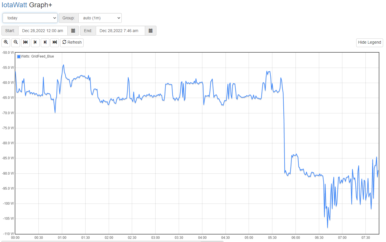
Here is a shorter timeframe overnight - my battery algorithm tries to Zero out the grid draw so the Blue should definitely not be flat all night
Craig
To answer the simple question, CTs usually are DOA or run forever. I can’t recall any failing while in service. They can give misleading results but that is usually caused by the CT being disturbed and opening up or otherwise compromising the split core continuity.
When a CT is actually “dead”, it does not have any output. I’m not seeing that. You don’t show the statistics of the plot, but I think that would show a minimum, maximum and average that is not zero.
Have you tried to reconcile the three mains against your meter? You have a complex system with battery. Maybe something else has changed to cause the battery to interact differently (what did it look like before you discovered this recent behavior?)
Hey Bob,
Nothing has changed that i am aware of - our meter box where the CT clamps are is a sealed enclosure and the meter readings are done wirelessly on a daily basis.
Yes it is complex and took a long time to get right which is why i seldom think about it now as it just hums along.
The IOTAWATT is in a sealed enclosure attached to the meter box.
Here is a graph that goes back to prior to the problem happening
and then from that date it just does the flatline.
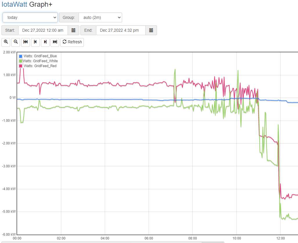
Here is todays graph
Whilst it is not a flatline it is definitely not representative of the true power flow - my baseline power draw of the house overnight is approc 1.2Kw per hour - this is serviced by 3 batteries (one on each phase) - i use Node Red to query the IOTAWATT every 3 seconds for the current house draw and then command each of the batteries to match that output (equal output from each battery)
So initially i thought maybe it was somethign wrong with my code - but checked that against the solar yesterday and it was definitely not a code problem - we were producing 16WK of solar in the middle of the day (verified by by the inverters and the IOTAWATT (which is clamped around both of the output cables from the inverters on all 3 phases)
However the power flowing out (as reported by IOTAWATT) was noticeably lower on the phase in question (but not in real life according to my 1/2 hour billing records from the power company
I need to dig through my spares pile today as i think i have a couple of extras that i purchased in my batch - plus the IOTAWATT has a couple of spare inputs.
So i think the way i will tackle this in order of ease is
- Cold boot the IOTAWATT and check
- Change the input of the CT in queston to a spare input
- If i have a spare then swap that in (but the rewiring is a PITA) so this will be a last resort.
Do you agree with this approach ?
Craig
I can’t say anything definitive as I have no basis of understanding how your installation works. Strictly addressing the question of whether the blue CT is working correctly:
I doubt that booting the IoTaWatt will change anything in an otherwise properly working unit.
Given that the input is actually measuring something as evidenced by the recent plot, I doubt the input is bad. The only unique component is the input jack and the burden resistor. Those either work or they don’t.
If you do move to a different input, be aware that the scrips, including all outputs, integrators and uploaders, use the input channel number when defined and not the name. So, plugging the CT into a different input and configuring it with the name of the old input will not automatically cause all those scripts to use the new input. They would all require editing to reselect the new input.
IMO the first step would be to replace that CT with another using the same input. If you don’t have another, I would swap it with the CT on another main both moving the CTs and the inputs so that each main is still going to the same input but with a different CT.
If the CT in question is in a sealed (by the utility) meter box, access to check it will be hard. I would attach a know CT with a known load on it to the input that has the blue CT now. That should isolate the problem to the input (of Iotawatt) or the CT cabling backwards. That is a pretty simple test. If it is the CT/wiring and does require the utility to come out, you might want to consider if there is a different location that might work.
Sorry - fogot about this thread - the CT was bad - replaced it with a spare and all came back and is working fine now
Craig