I have my own board up and running (schematic 100% Iotawatt V5 clone).
Before installation I tryed some measurements in my workshop under constant conditions (Germany 230V).
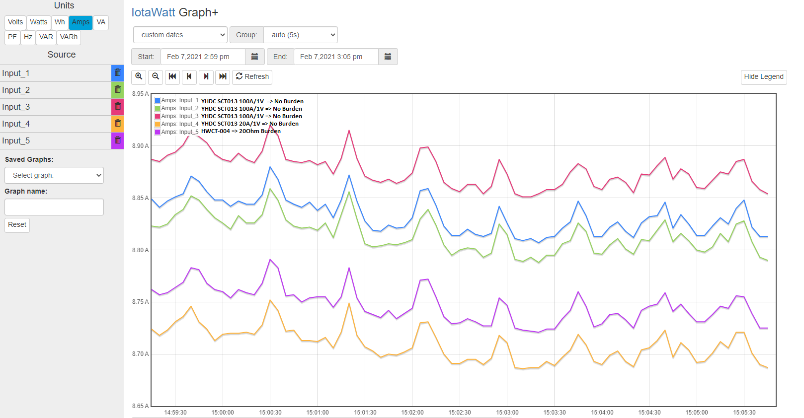
I put 3pcs SCT013 100A/1V + 1pcs SCT013 20A/1V + 1pcs HWCT-004 on a “test-line” with a 2kW heater. I have no burdens for the SCT013 installed but one 20Ohm for the HWCT-004. Further I measured the current with my Fluke 77 multimeter an a cheap clamp-on current meter.
The Fluke says 8.35A the cheap clamp-on says 8.5A
The 5 CT gave me values between 8.7A and 8.85A.
Due to the fact, that I dont know if the Fluke is accurate I will try to get another one the netxt days to verify the measurement.
2 Questions:
If I can confirm, that the Fluke is correct, is it possible to “calibrate” the entire Iotawatt current measurement, so that I can go down the ~400mA? Or is this just the possible accuracy and I dont have to worry?
Is it possible to calibrate the single CTs so that say come closer to the same value? On the SCT013 I can manipulate the “calibration-value” at the Input-configuration, but would this be a good way to change the 100A/1A from Calibration 100 to lets say 98 and so on ?? Or will this bring faulty measurements on other currents, temperatures, etc?
And what would be the way to calibrate the HWCT? I dont have a Calib. value at the config page because it is pre configured.
Or am I just to squeamish and my readings are as good as they can be?
The spread between the five CTs is a little under 2%. That’s not too bad for YHDC CTs at this very low current. I’d put my money on the HWCT-004 for best accuracy, the others seem to be about +/- 1% of it. What is the tolerance of the burden resistor?
The other issue is that these all vary from the Fluke meter by nearly 5%. Could be the Fluke, but I doubt it.
The primary calibration of the IoTaWatt is via the reference shunt. I use 0.2% components for that. Using the Fluke, measure the voltage after the shunt. If it’s not 2.5 (or whatever value shunt you used), override the shunt reference value with what the Fluke reads in the config file.
The 20Ohm burden for the HWCT is 1% tolerance. I measured one => 19.955 Ohm (measured with Fluke 8840A 4-wire-mode).
The YHDC have build in burden, as you know.
So I will not think about the spread any further.
But the difference between Fluke and iotawatt…
The 2.5V shunt I used is 0.1% Tolerance. Measured value on the running board => 2.5006V (measured with Fluke 8840A) EEPROM is set to 2500mV
I just repeated the measurement with a smaller load (400W halogen floodlight). The Fluke77 says 1.71A, the 5 CTs on the iotawatt say 1.71A to 1.72A. My Fluke 8840A confirmed the current reading (has only range up to 2A). So I would say perfect.
But, then changed again the load to the 2kW heater (full power) => Fluke is again ~400mA below the iotawatt readings as described in first post.
Next reduced heater to half power => Fluke is 5.12A and iotawatt is 5.33A to 5.38
so either the fluke is drifting away on higher current or the iotawatt is drifting. Hopefully I can organize another Fluke with a current reading range up to 10A the next days from my company office (thanks covid I am at the homeoffice actually). I will post the measurements as soon as I get them…
If you have any other idea to find and isolate the reason for the problem let me know
Sounds like you know what you’re doing. You do need a more reliable standard as an arbiter. With the three data points, it looks like both the IoTaWatt and the Fluke 77 are pretty linear, it’s just that the Fluke seems to have about 5% less slope.
Have you checked the bias voltage vs. the ADC reference voltage? Here again I use low tolerance resistors for the voltage divider on the op-amp. IoTaWatt has logic to detect and compensate for some drift, but it is restricted to only a few ADC counts. If it is way off from center, it will affect rms current. The production IoTaWatt manufacturing tests check that the bias is within two counts of center as measured on all of the inputs.
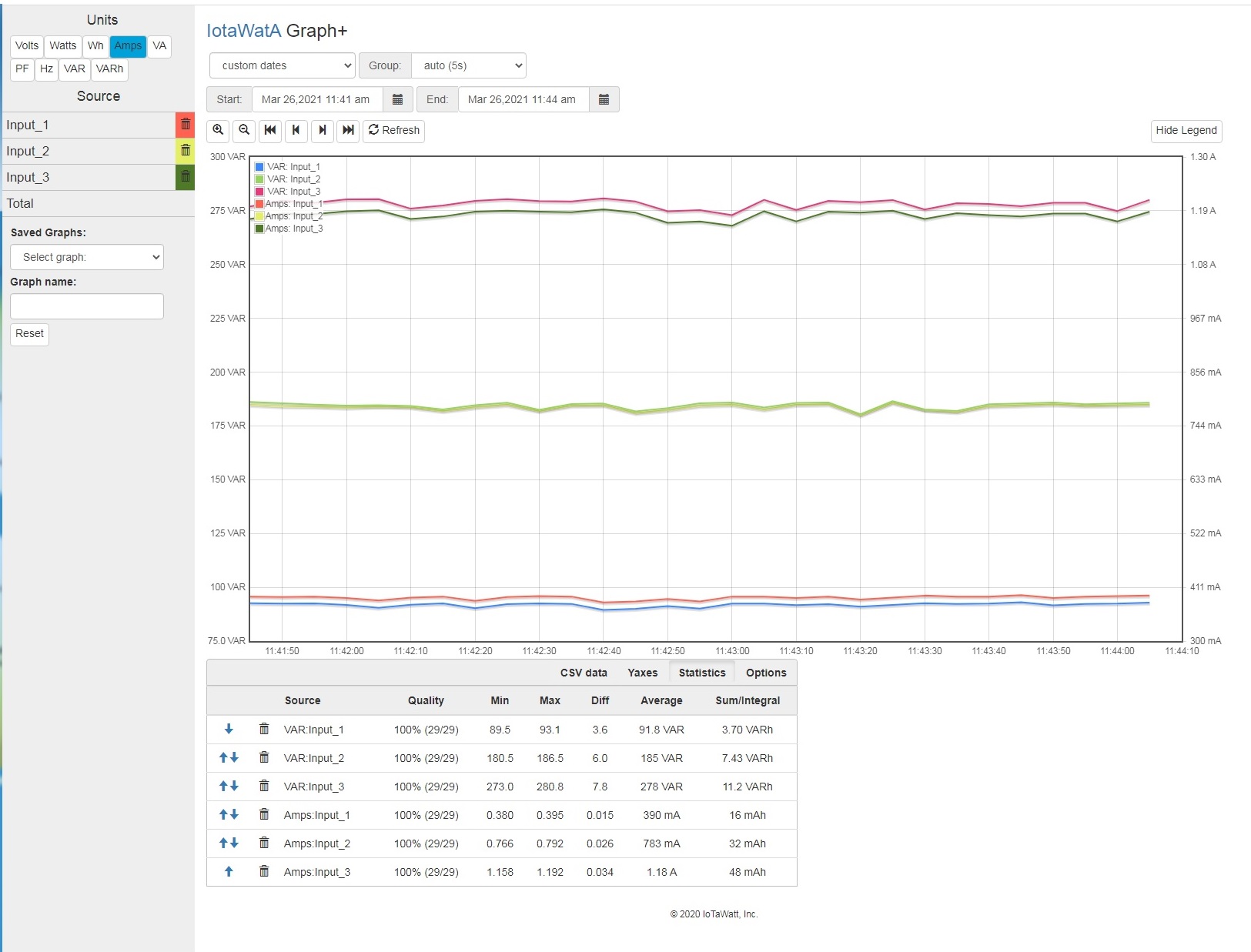
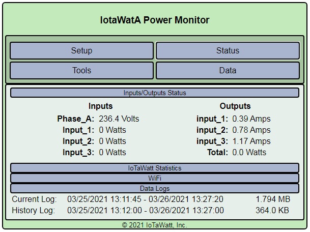
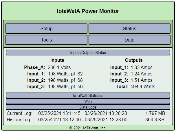
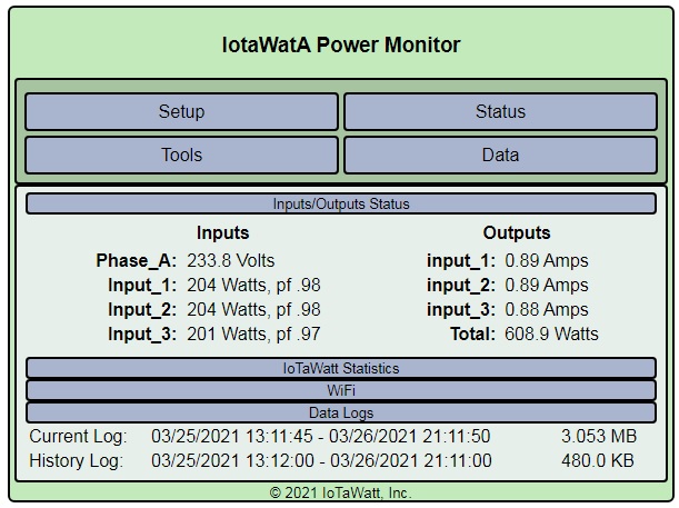
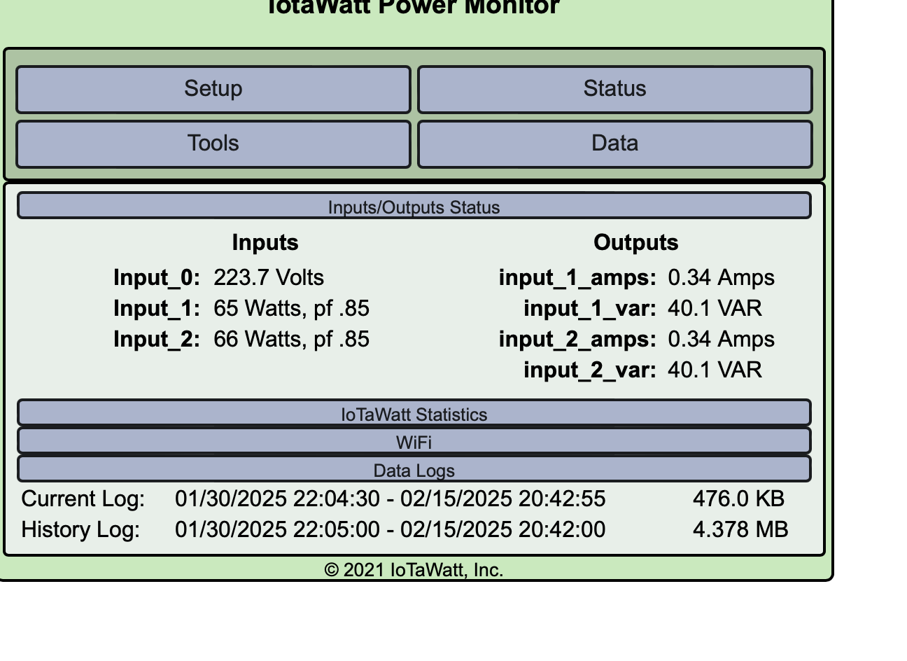
I have testing my device. Have set correct voltage and calibrated CT as show correct power. But when looking in Graph+ Amps, VA, VAR when in real not power, then show value, as ir real is 0. Looking pictures. This is my fault in configuration or in circuit?
Not really enough information to understand what’s going on here. A few observations:
I see that you are using an incandescent light to test. The power factor should be 1.00 with that load, and the VAR should be very small or zero.
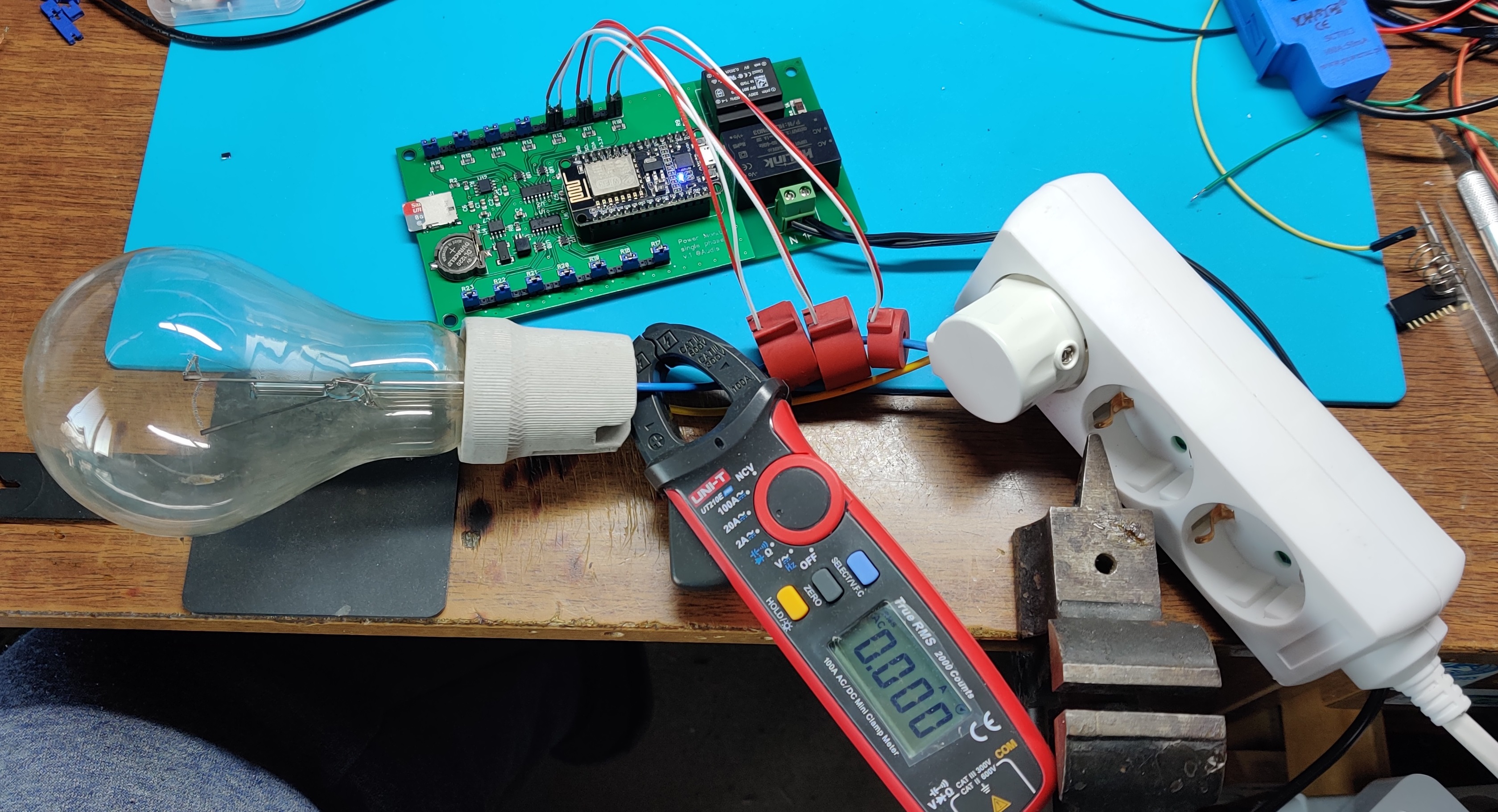
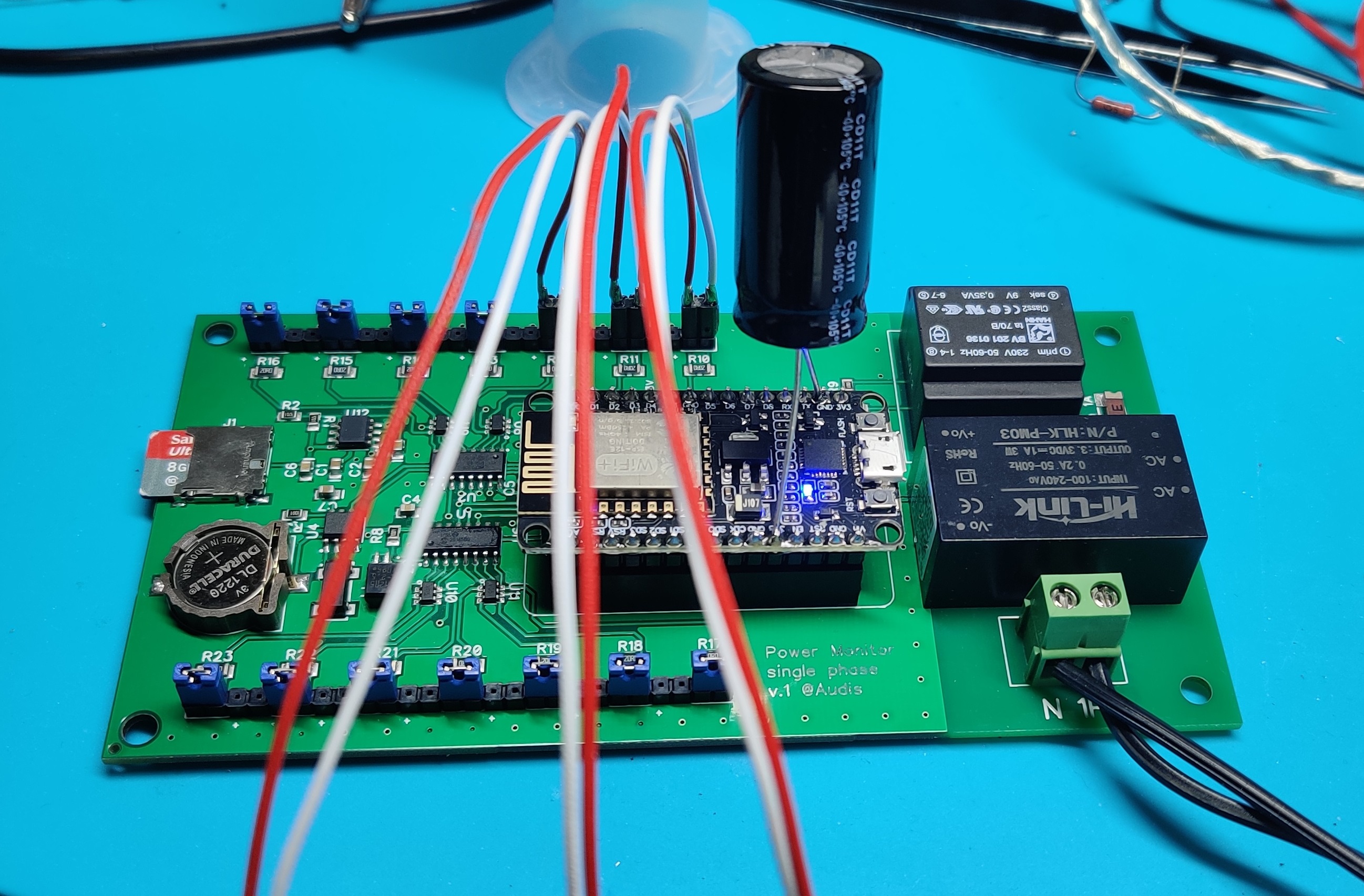
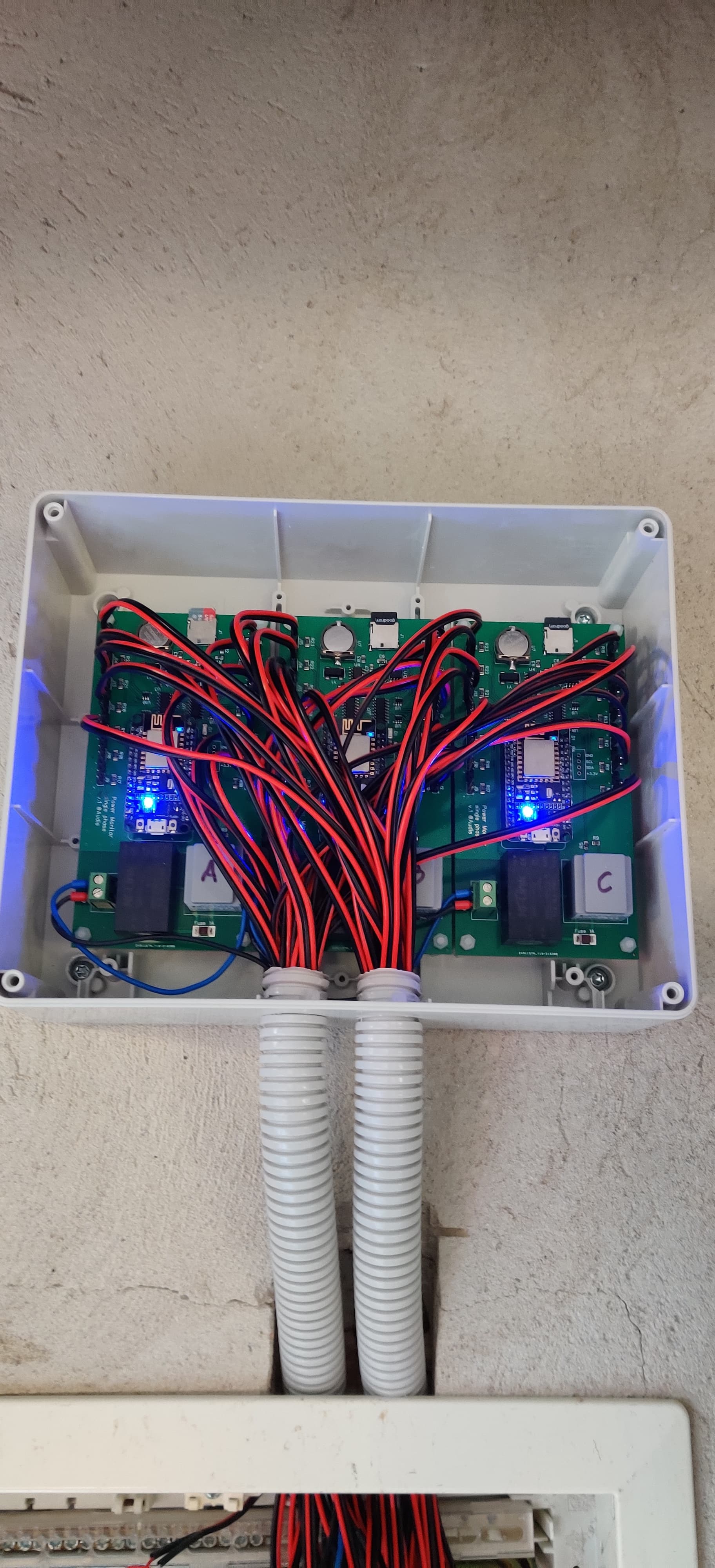
I see that you have a small transformer on your board, presumably that is your VT. In general, lightweight transformers tend to have a lot of phase shift. If you have not calibrated the shift of this transformer, you will probably never get accurate power-factors or VARs. Amps however should be unaffected by the VT phase shift.
You also appear to have a DC power supply on the board. If that runs off the 230V it should be fine, but if it runs off the 9V from the VT, there could be issues with it corrupting the AC waveform and thus your accuracy.
You have three different CTs, all showing different Amps, but resulting in the same power (Watts). I don’t know how you have it configured, but the indication is that something is very wrong with that configuration. All that should be required is setting the correct phase-shift for the VT, and the correct turns and phase-shift for the CTs.
EDIT: While I can understand most of your post, it is not clear to me what you are saying. If I could suggest that you try making your post in your native language and using google translate to produce English.
Sorry for my bad English.
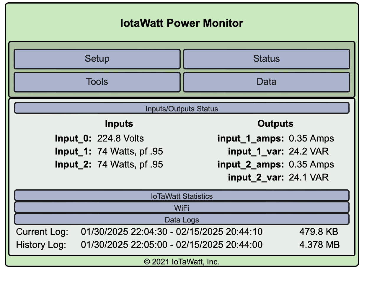
Thanks for information and idea. Problem have solved.
The problem was in China 3.3V power module. He has approx 100mV pulse… I put 2200uF capacitor and now looks fine
Better than my Chinese. The nodeMCU has a 3.3V LDO regulator. You would do much better to feed the 5V pin and let the DEVkit make the 3,3V. Still probably need to smooth out the 5V, but any ripple in the 3,3V gets picked up in the ADCs.
@Audis are you satisfied with the BV20 HAHN VT transformer that is visible on the picture of your prototype?
Did you apply any phase shift (as suggested by @overeasy) in the configuration to have correct measurements?
@wwk BW20 have lot of heated that have changed to other. Later check model and upload pictures. But measure voltage is not very accurate when use this type. For more accurate better is use VT on wire same as use CT.
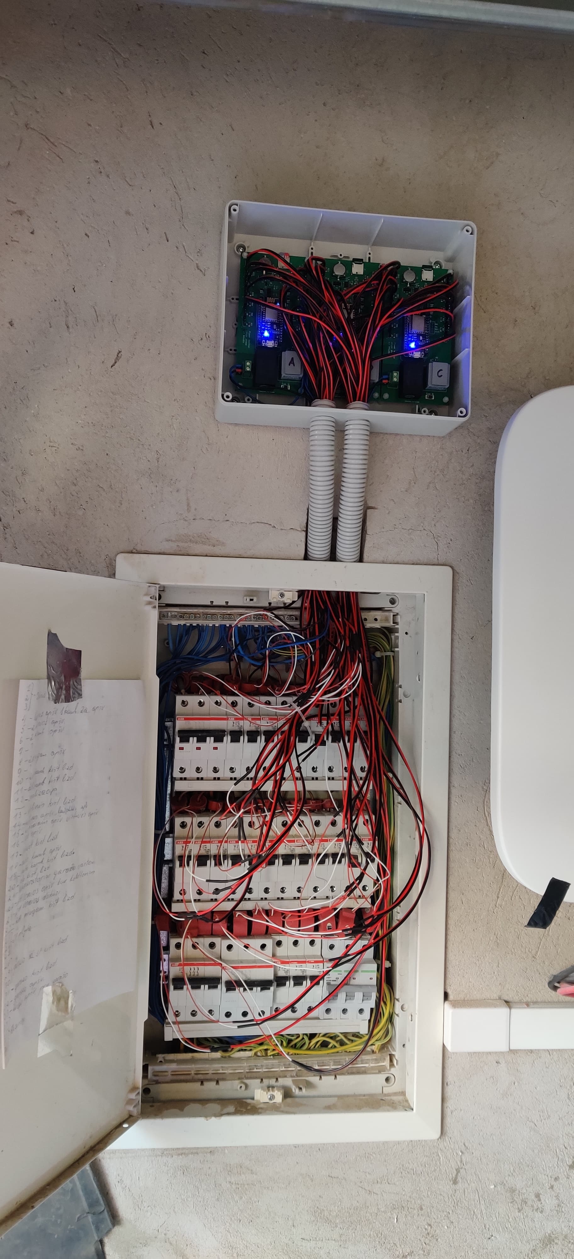
I have maded 3 PCB for each phase.
I have before problem with big pulsation from Hi-Link power source. But solved put big capacity capacitor.
Using HiLink and some good pcb-mouting VTs is very tempting for me.
I would like to avoid having VT with a wall-mount connection but I did not see any of pcb-mount VT type on the list of IoTaWatt system.
@Audis thank you for the pictures.
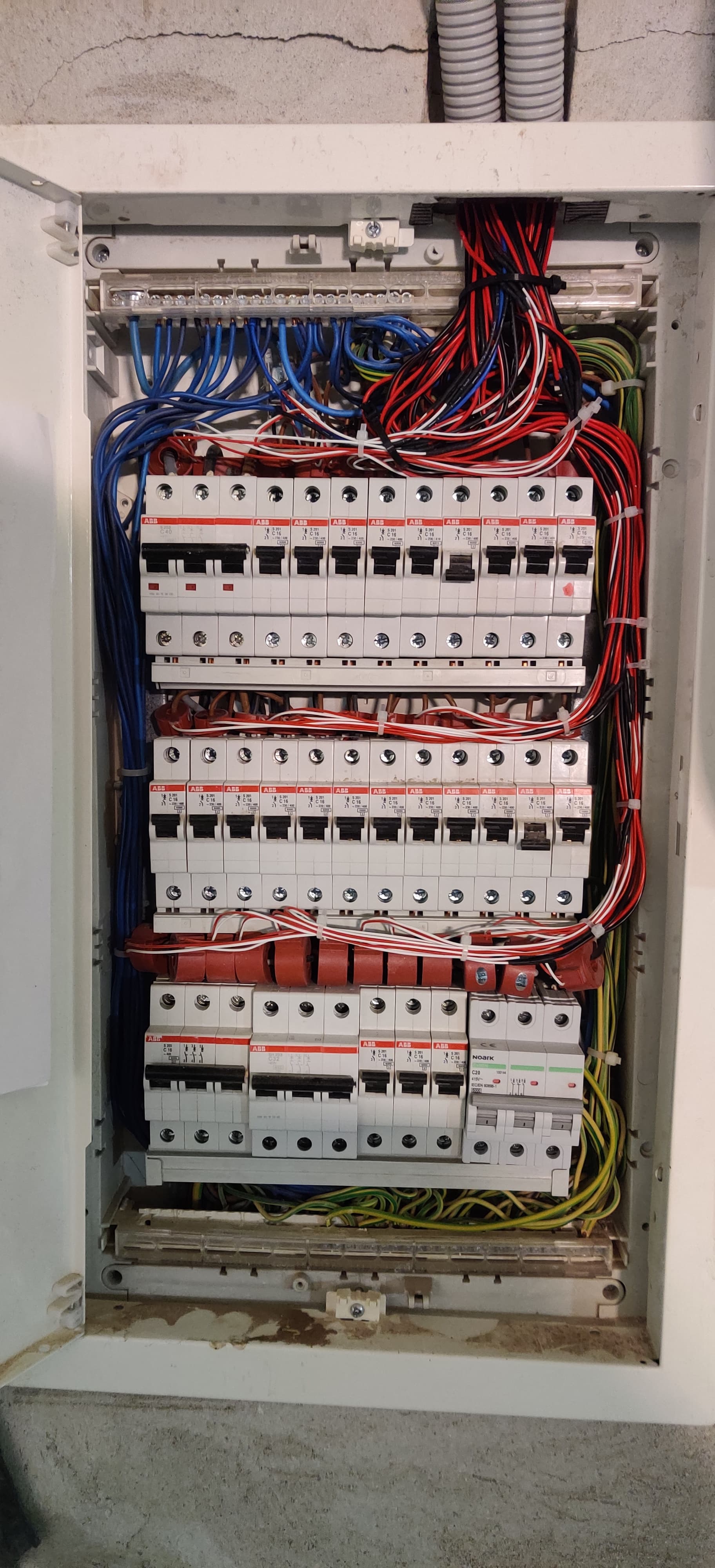
I have a similar problem with the space and the number of circuits to monitor.
What are those CT (the red ones) you used. Are they of good accuracy?
I need ~30 CTs 20-50A.
I wrote to ECHUN (ECOL09) for the quotation but the overall price with the shipment to Poland (where I live) is too high (290 USD for 27 pcs).
I’m also tinkering with that small Hahn transformers and same HiLink 3.3v power source. And wondering are my issues down to that lightweight transformer, or there is something else going on.
Doing testing with 75w incandescent light . With Generic 240v I get values way too low and with a strange PF:
That says to me that the BW20 is NOT a good choice and they used something else to get decent results. Bob has tested several different VTs and provides the calibration factors for them. I would suggest picking one of them if you care about accuracy.