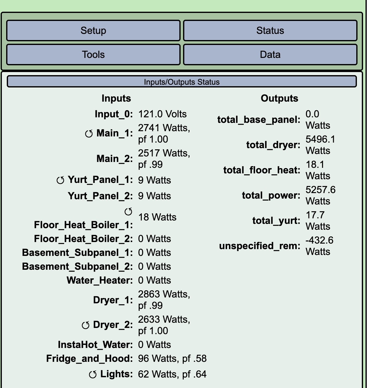
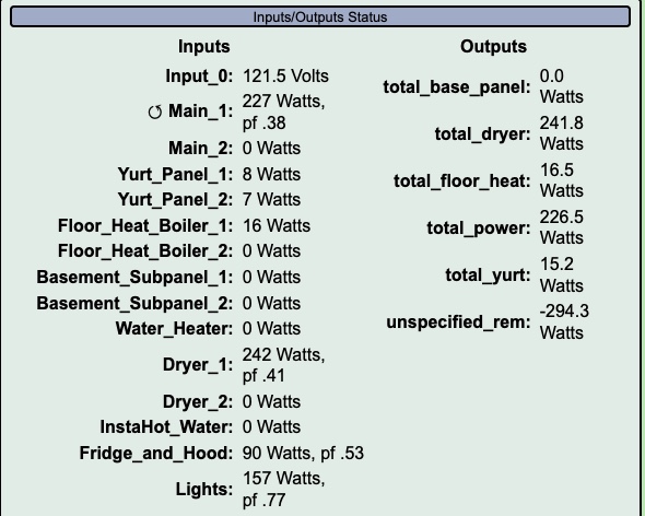
I took a screenshot of my Input/Output status when my Dryer was shown drawing more power than was coming in my mains. I’m trying to figure out what I’ve done wrong in install/setup/configuration.
While human error is clearly possible, I double checked my output formulas after seeing this, and was also careful to get the CTs facing the right way during install.
There is no solar on this system, and no inputs are set to allow ‘reverse’
My misc output “unspecified_rem” is showing negative even though it is powering all the outlets and fans in my house, plus washing machine and more.
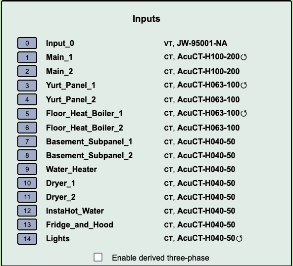
I also noticed that one of each of my paired circuits shows the counter-clockwise moving arrow. My guess might mean “reversed CT”. Is this accurate? Does that mean that in each pair I need one CT pointing towards the load and 1 CT pointing towards the panel?
You can see that the drum motor is drawing ~200W and that is at 120V, so it’s only on one leg of the circuit. You are probably measuring that leg and doubling it, which would always overstate the usage by ~200W.
The correct way to measure three wire circuits is to run both wires through the CT in opposite directions, or use two CTs, one on each of the red and black wires. You can read up on this in the docs here.
Your questions about the reversed arrow in the display is explained in the docs here, but absent PV generation, you can pretty much just ignore it as it’s only telling you that the CT is backwards but the IoTaWatt has recognized that and corrected the measurement to be positive.
Thanks for your help.
The reverse was well explained in the doc you referenced. I’ve reversed the CTs in the software by checking the box.
But I don’t think my other question is answered yet. Here’s why.
I had read the 240V docs you referenced during setup, and has already installed 2 separate 50A CTs on the red and black wires of the dryer. They are being measured on two different inputs (not doubled), then combined in an output calculation. The image shows the dryer using 2863W and 2633W (on the two inputs) for a combined 5496.1W at the same moment that the mains are reading a combined 5257.6W.
Given that my ‘Misc’ output is showing -432W and I was probably using 100-500W, I’d estimate the total miscalculation to be 500-1000W on either the mains or the dryer legs.
What else could explain this discrepancy, given that the 2 CTs are in use as described in your docs?
Thanks!
That was my bad on the dryer. Had another case in the last few days with a single CT doubled dryer. Didn’t look close.
I’d like to try to validate the dryer and mains CTs. could you put the mains CTs on the dryer wires alongside the dryer CTs and run it for a minute or two capturing a status display?
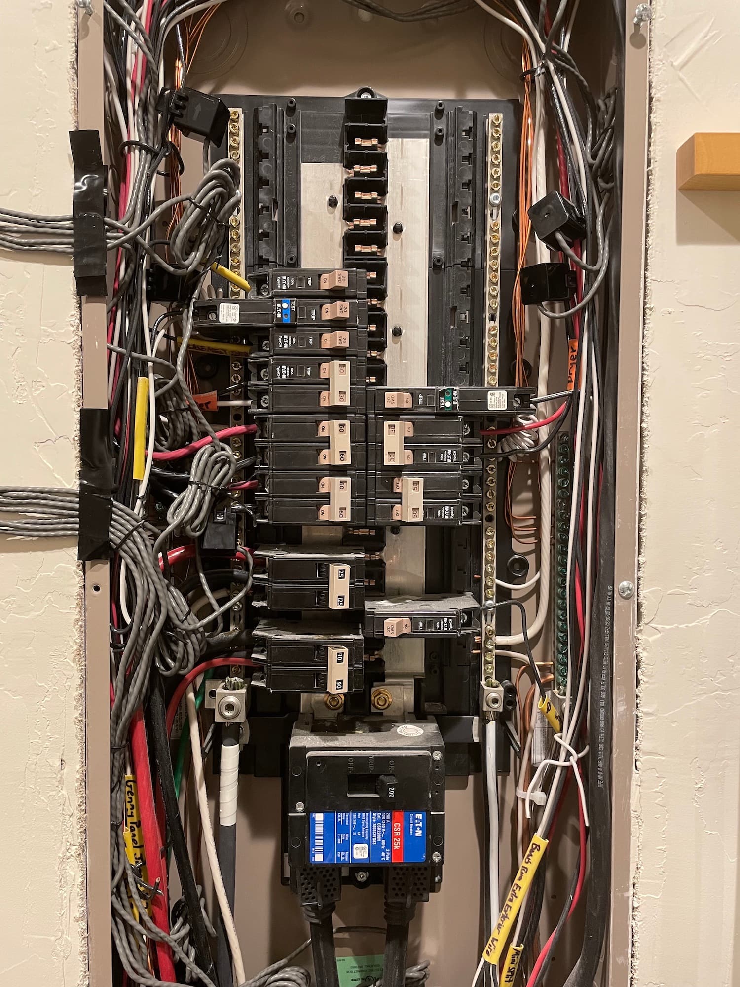
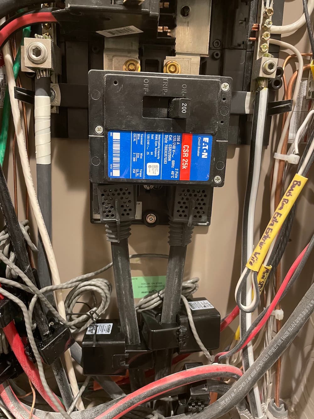
Can you also post a picture of the panel with the CTs installed before you move anything?
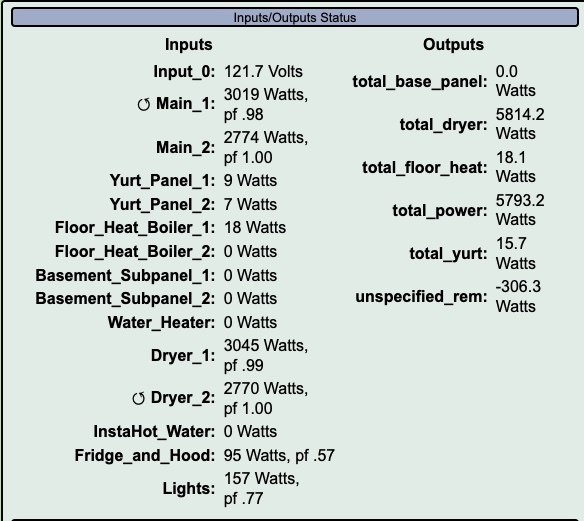
Next, the test of putting the 200A Mains CTs onto the dryer wires and running the dryer. Here are 2 screen shots, one with just the drum going, and one with full power.
So these readings were within ~20W. I don’t know what a normal tolerance is. But the readings I shared in a previous post of this thread show a difference of perhaps 500W+, which was not replicated in this experiment.
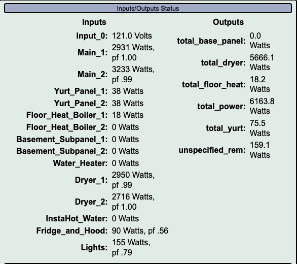
Main_2 not quite as much but still under 1% (0.85%) It should be closer and the power factor should match. Can you inspect that CT and be sure there is no impurity on the otherwise smooth mating surfaces of the iron cores?
Looking at the before picture of the mains CTs, I’m wondering if the way the cores of the two CTs are against each other is causing them to read low. Ordinarily they would be installed with opposite orientation, but here they are the same way (reversed by IoTaWatt). I’m thinking maybe the magnetic flux in each may be somewhat diminishing the other.
Can you move them back, reversing Main_1, and find a way to introduce an inch or more of spacing between them to avoid the magnets touching and again checking the mating surfaces of Main_1?
I got readings that look more plausible. If the following readout matches your expected tolerance, then I’m guessing the culprit was with the original install and lack of good contact.
I ran the test 3 times, and all the screenshots were about like the one below. No negative values.
What do you think?
As you say looks plausible. You would know better if the unspecified is in the ballpark. I’m assuming that Main_1 corresponds to Dryer_2 and visa-versa.