So my house has two 200A panels. One of these panels has a 125A breaker that feeds my shop.
I have the basic kit and also ordered two additional 200A CTs for the 2nd panel.
The iotawatt web site says (re “Double” option) :
”In North American split-phase power systems (120V/240V), all circuits are assumed to be 120V. When this option is selected, power will be computed using double the value of the reference voltage, or nominally 240V. Use this for 240V circuits where one CT has been applied to one of the conductors and there is no neutral (white) wire used by the appliance. Typical circuits would be Water Heater, Water Pump, Mini-Split Heat-Pump. There are other ways to monitor 240V circuits as well.”
My well water pump definitely has four wires going to it (ie a neutral) but I think only 3 at the well head. Should I just use 2 CTs here?
Also, my dryer is definitely a 4 wire cable and does not have bonded neutral, should I also use two CTs?
My total list of 240V circuits is:
Shop (which I assume has to be 2 CTs because there are circuits on both legs
Furnace (electric geothermal furnace with an external glycol pump - not sure how the pump is wired as it can be wired for either 120 or 240)
Well pump controller (and pump)
Range
Oven
Hot Tub
Dryer
Any advice on 2 CTs vs 1 CT or do I really need to inspect how each one is wired?
What if I started with 2 CTs on each, and then it the consumption between legs is somewhat identical, switch to 1 CT and select double?
And what are the “other ways” to monitor 240v circuits?
Generally speaking the double is used when the device only uses 240v. I would expect most well pumps to only be 240v, but if there are control circuits above for pump control or report, they may operate off of 110v. A lot of cases are just that – heavy draw users at 240v with controls , gauges, displays at 110v.
It’s never wrong to use 2 CT’s and not double. If it’s a huge draw item (like a dryer, range) it’s likely the 110v component is very small compared to the main draw. Some people just decide to ignore this minor difference and double (double the larger leg errs high, double the smaller errs low, take your pick). Putting on two CT’s and going through the normal modes of operation is a good way to tell how much it matters (if at all).
Just because manufacturers are cheap, if the device itself has 4 wires it’s likely it uses 110v internally. That doesn’t mean the electrician that wired it did it correctly of course, but if you see 4 wires using two CT’s is the most likely correct way. Unless you run out of CT’s and don’t need high accuracy on those, then just pick one.
Thanks, looks like I have everything set up, except for my 200A CTs for the first panel.
Sucks that I ran out of inputs, I chose the oven, but didn’t have room for dryer or range. All three are “user driven” unlike some of the other big ones (hot tub, furnace) which are more environment driven.
The other interesting thing is the well controller bounces around each leg between 0-9 W randomly. It is a variable drive so it must be in a “ramped down” rather than “shut off” state or something. It also has a cooling fan which I would think would probably be 120V along with the control brain.
I guess I will run for a few days and see how things look.
I’m trying to scope out my solar system design – and I got to the point where I realized I was over-sizing it based on everything’s maximum capacity. Now that a lot of the inverters do grid pass through up to 200A, I realized I didn’t have to get it perfect (at least for when the grid is up), so trying to see if I can make a single inverter (the new Sol Ark 18k) cover everything vs two 15ks.
A prior house I had two 200a panels, I bought an iotawatt for each. At the most recent house I had one panel very full, so I just used both iotawatts and all the CT’s.
There are always surprises. I’m working today because I couldn’t reconcile my 200a input and the CT’s I had, and found a landscape transformer with lights turned off actually was drawing 90w full time just to keep the lights ready to turn on (they were wifi lights so it’s not a huge surprise but a bit of one).
There are always surprises when you dive into the iotawatt data.
Yes, I considered two units but I was trying to get maximum bang for the buck – so getting 2 extra 200A CTs seemed easier and cheaper and then all the data is one place too.
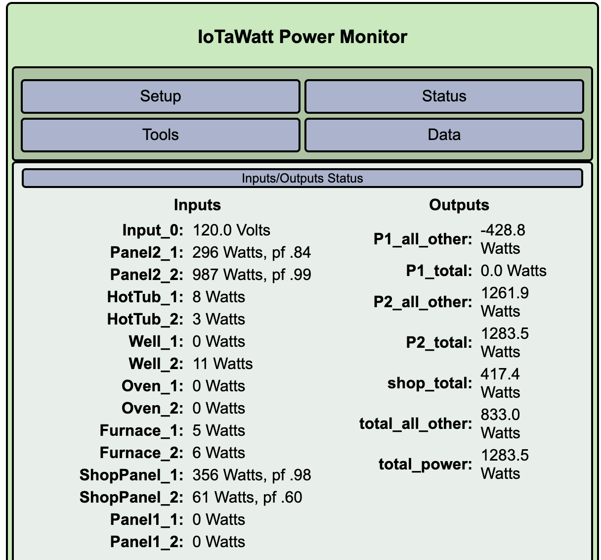
While some of the circuit info is interesting (the hot tub OMG!) the panel total numbers are the most important to me. I need to find out if code allows me to pop two knock outs and drill a hole through the stud between both panels to route the CT wires across. I would think this is ok for low voltage without a nipple/connector but there’s always something surprising in the NEC.
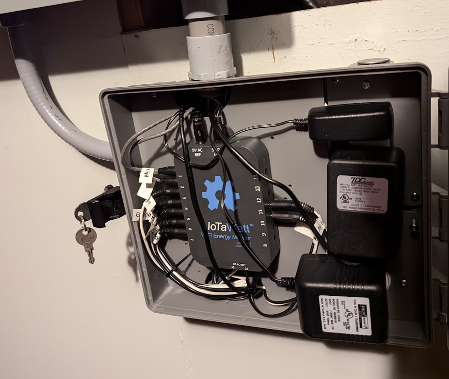
I assume people just sandwich the 5v power and 9v reference cables under the break panel fascia on their way to the outlet?
I am not an electrician but I’m pretty sure you can’t have wires going out a knockout without a connector (sharp edges on the metal and such, probably chance of critters crawling into the hole). But to be sure check with a real electrician. Or spend the 50 cents.
Postscript: I just realized you meant the stud up against the size. Not sure there. You can also go out the bottom thru the stud and back up. If you find out the real answer about the stud please post.
Postscript 2: I put my iotawatt in a separate box and run conduit into the panel for the low voltage wiring to the CT’s. Actually two pieces of conduit, one I ran two 120v circuits for outlets for the reference transformers for each leg (overkill with both), and one for low voltage. I’m not sure the conduit needs to be separate, but the HV and LV in the separate plastic box has to have a barrier. This is a sprinkler box that works nicely for this.
I was able to figure out the hot tub, dryer, range, furnace/glycol pump all used both legs equally, so doubled those and freed up some CTs to bring on those new circuits. I basically watched both legs and created an output that was leg 1 - leg 2 to see any big differences.
BUT the oven is a combo unit with a built in microwave. Figured out that for the oven it uses both legs but for the microwave just one, so a huge asymmetry of power, so that has to keep two CTs.
Also found my breaker panel had the labels for range and oven were reversed!
It also worked out nicely with 7 CTs in the first panel, and 7 CTs in the second panel which made the cable routing neater.
I’d double check the dryer. Most use a 120V motor for the tumbler and 240V for the heater. The heater is a much bigger load so you might not be noticing the motor load. This is a good candidate for the reversed conductors in one CT as described in the link above.
Also, not clear where you have the IoTaWatt but sounds like you may have placed it inside the panel. That would be a definite code violation and the IoTaWatt is not safety certified for that.