New user here and trying to get an understanding on CT orientation. In reading the CT Basics docs it appears that for North America split phase the CT’s on the main legs need to be orientated differently. Is this correct? That is the way I have them installed and compared to another energy monitor that IoTaWatt is replacing the reporting seems accurate.
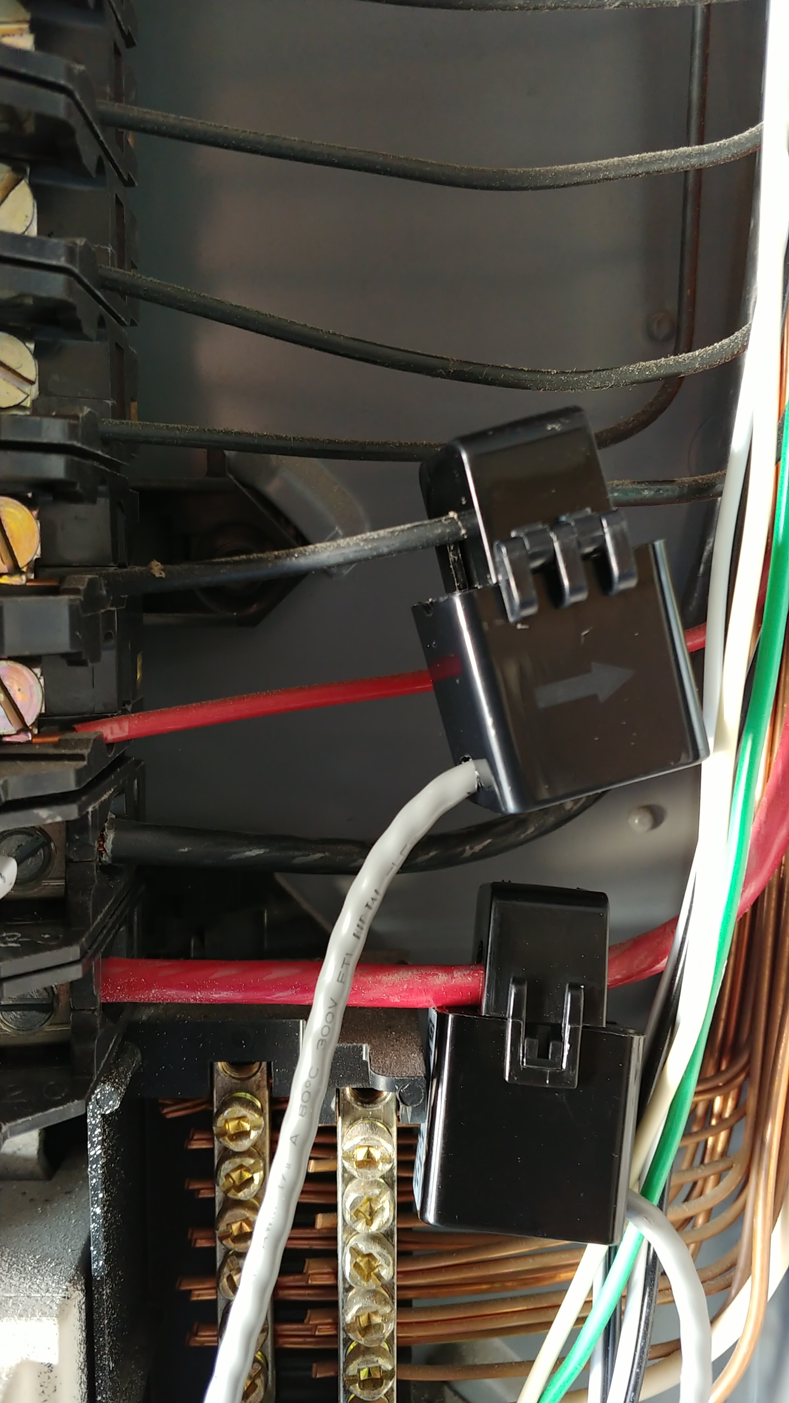
In the attached photo please note the different orientation of the CT’s for additional circuits.
These are and both configured as a AcuCT-H040-50 with double checked. The both appear to report correctly as compared to other sources. The one on top is orientated with the arrow pointing to the load side which is a 20 amp pool pump circuit. However, the one on the bottom is orientated with the arrow pointing to the source or line side and is a 40 amp air handler circuit. I originally had this CT with the arrow pointed to the load side but the app showed the reverse icon. I know I could have fixed it with the reverse toggle but I instead just reversed the CT.
My question is why do these exact same CT clamps on the same phase have to be reversed in orientation?
I moved the CT from the red wire and placed it on the black wire. I also changed the orientation with the arrow pointing to the load side and no longer get the reverse icon. So I guess my question is now what is the difference in the two wires and the effect on the CT orientation.
Except for the reverse arrows, It’s a difference without a distinction. With US split-phase, there are two different phase orientations that alternate as you go down each side of the panel. In your case, the electrician appears to have observed a convention where the black wires correspond to one phase (one of your main lines) and the red corresponds to the other. With split-phase, these two are exactly 180° apart.
Your reference transformer is plugged into one of the phases. It is 180° out of phase with the other. So lets say your VT is plugged into the same side as the black wires in those two circuits. It is 180° out of phase with the red wires. So when you put a CT on a red wire, it will show a “reversed”. If you physically reverse it by pointing the arrow the other way, you will cause it to output a signal that is 180° shifted, and matches the VT signal.
Now for the difference without a distinction. IoTaWatt will automatically reverse or use the absolute value of a CT reading. So there are those annoying reverse arrows, but the results are fine.
With the mains, you can also just put the CTs in any orientation and get correct results. The exception is when there is solar and negative values are not just reversed CTs, but indicate that power is being exported (-sold) rather than purchased (+bought). That’s why we try to have the mains installed in opposite directions and check “allow negative values” for those CTs in setup.
Note: CT orientation is fail safe with split-phase (or single-phase), but is critical with three-phase.