I have had my IoTaWatt since 2021 and it’s been working fine. Glad to see there is still activity in the IoTaWatt community. Great device giving invaluable data!
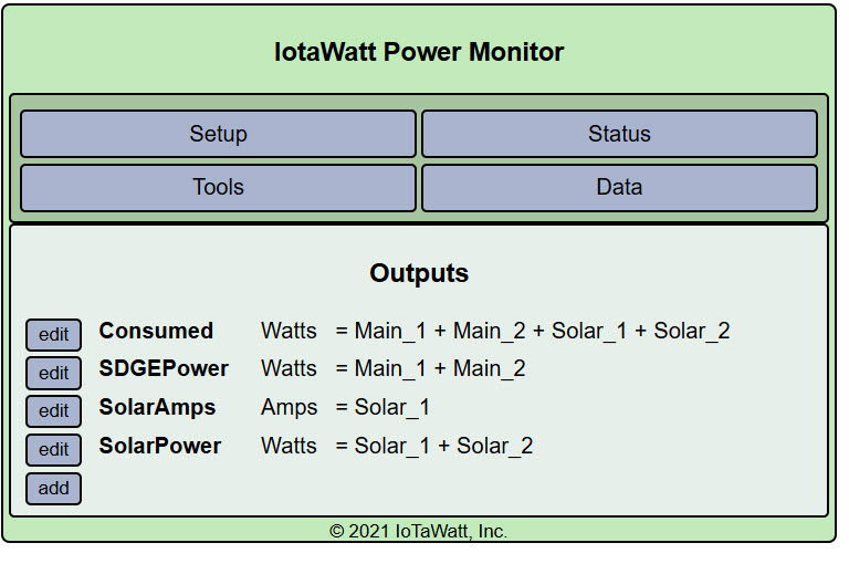
I have the 5v power supply plugged into a UPS for protection from surges, and the AC monitor to a regular outlet. I use CTs to monitor the 2 main wires from SDGE and the 2 wires from my solar inverter. I then calculate Consumption watts by adding the mains and solar watts. Have not had any power outages or restarted the IoTaWatt for a couple years. Data as viewed on the graphs is consistent.
Yesterday, after we lost AC power for about 2 hours, and everything restarted (had to wait for wifi to restart before starting the IoTaWatt) and I was getting my normal graph output, I noticed a much higher consumption reading than normal. It was about 6KW instead of 1or 2 KW. The SDGE meter was reading a negative approx. 2KW flow.
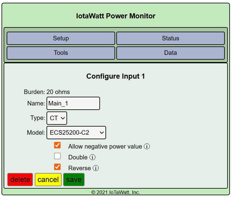
So I tried reversing the CT signal on the Input Setup Configuration for the 2 main CTs. That appeared to fix the problem.
But I don’t understand why a restart of the device would cause the polarity of the CT output to reverse? And it was just for the mains, not the solar.
Could SDGE’s repair of the outage have switched polarity(?) of the mains? I would think current in vs current out should have stayed the same. Puzzling.
It should not affect the mains polarity which is relative to the polarity of the VT. If you did not reverse the VT, it should not matter if the utility reversed L1 and L2.
Solar inverters phase lock with the mains.
As above, should not matter. But there is a caveat:
I see you are in California and this is not common there, but some apparent split-phase services in the US and Canada are actually two phases of a three-phase supply. This is evident by a phase to phase voltage of 208 rather than the usual 240. It is most common in apartments and condos. If you have that, you would know because you would have setup with “enable derived three-phase”. You would also probably have a unique solar inverter capable of supplying that.
Can you post a graph of the individual mains and solar (if you have two on the solar else just the one) for the day that this transition took place?
The voltage between phases A and B is 243 VAC. And all the wires on the poles were only 2 phases. So I don’t think a 3 phase system is applicable here. Note, about a year ago we were undergrounded, but no abnormalities occurred.
I have attached 6 screen shots:
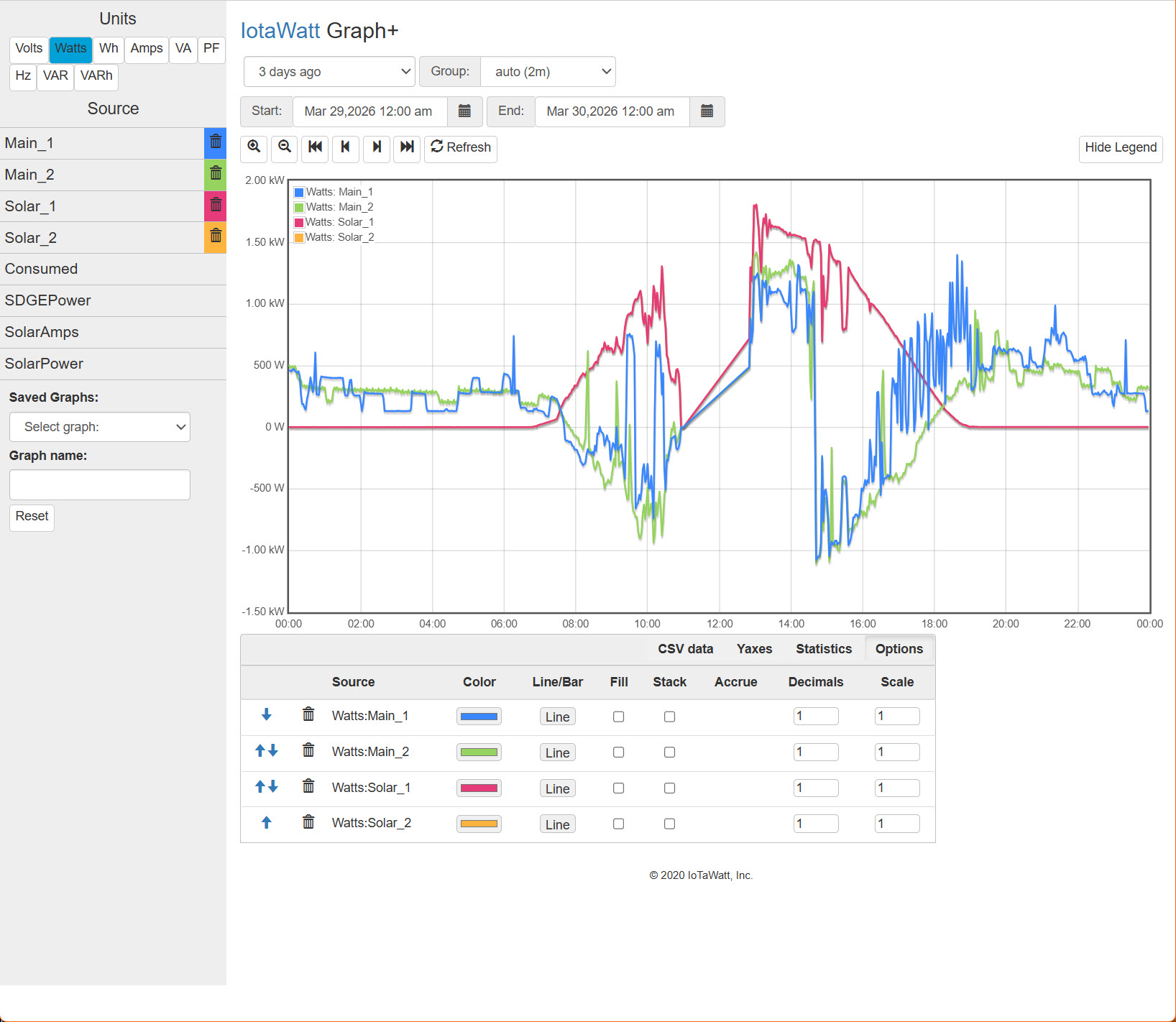
The plot you asked for of Main1 and Main2, and Solar1 and Solar2, showing the outage. Note that the outage occurred about 10:55. At that time solar output was pushing current back to the mains. Then at 12:50 power was restored. Solar shows positive current as pre outage, but the mains now show current being drawn from the utility not pushed back. At 14:35 I reprogrammed the mains inputs by switching the polarity switches. The mains current now again shows negative as the solar produced more than I was consuming. Note that the two high current spikes about 9:30 and 10:20 are due to the dishwasher running at that time.
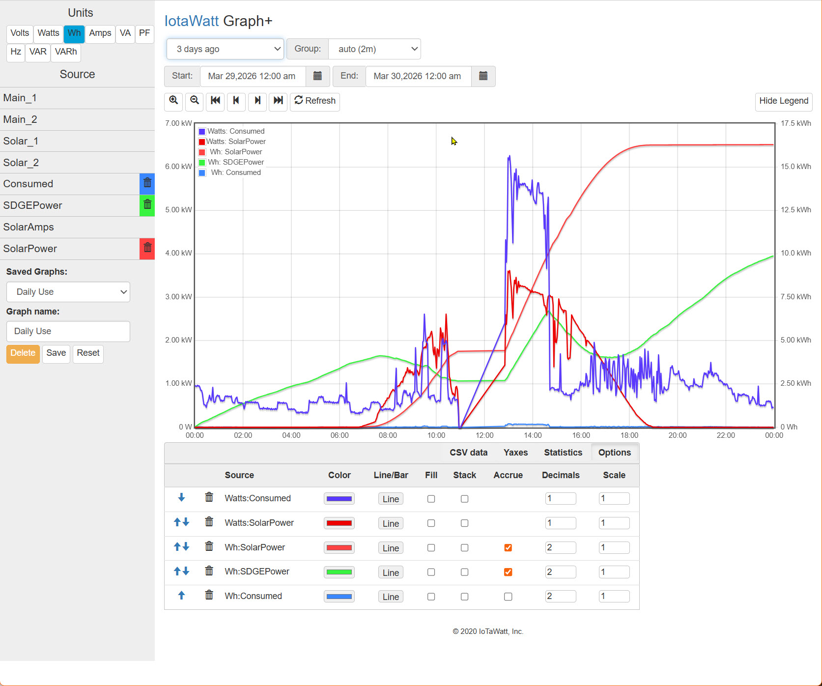
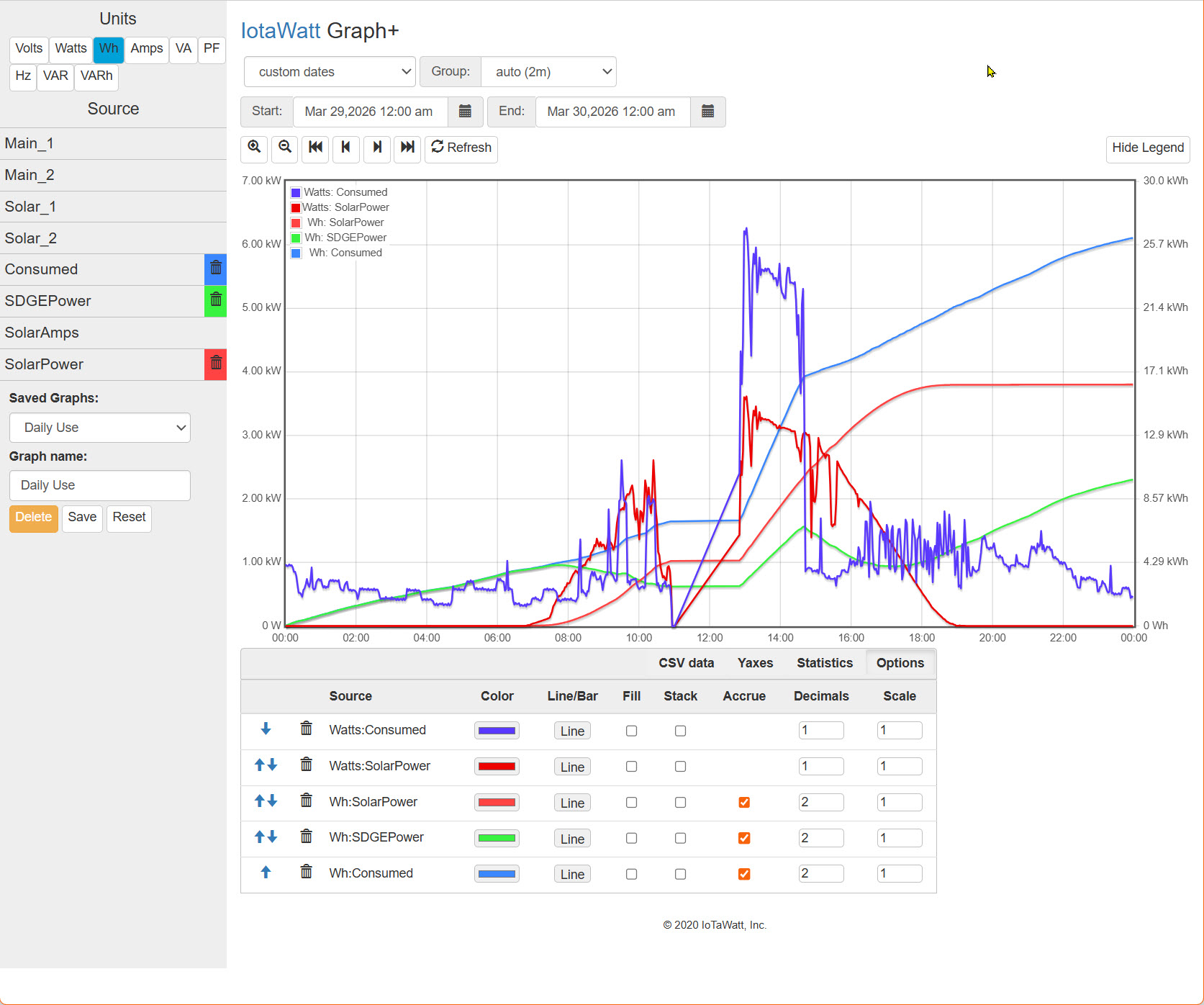
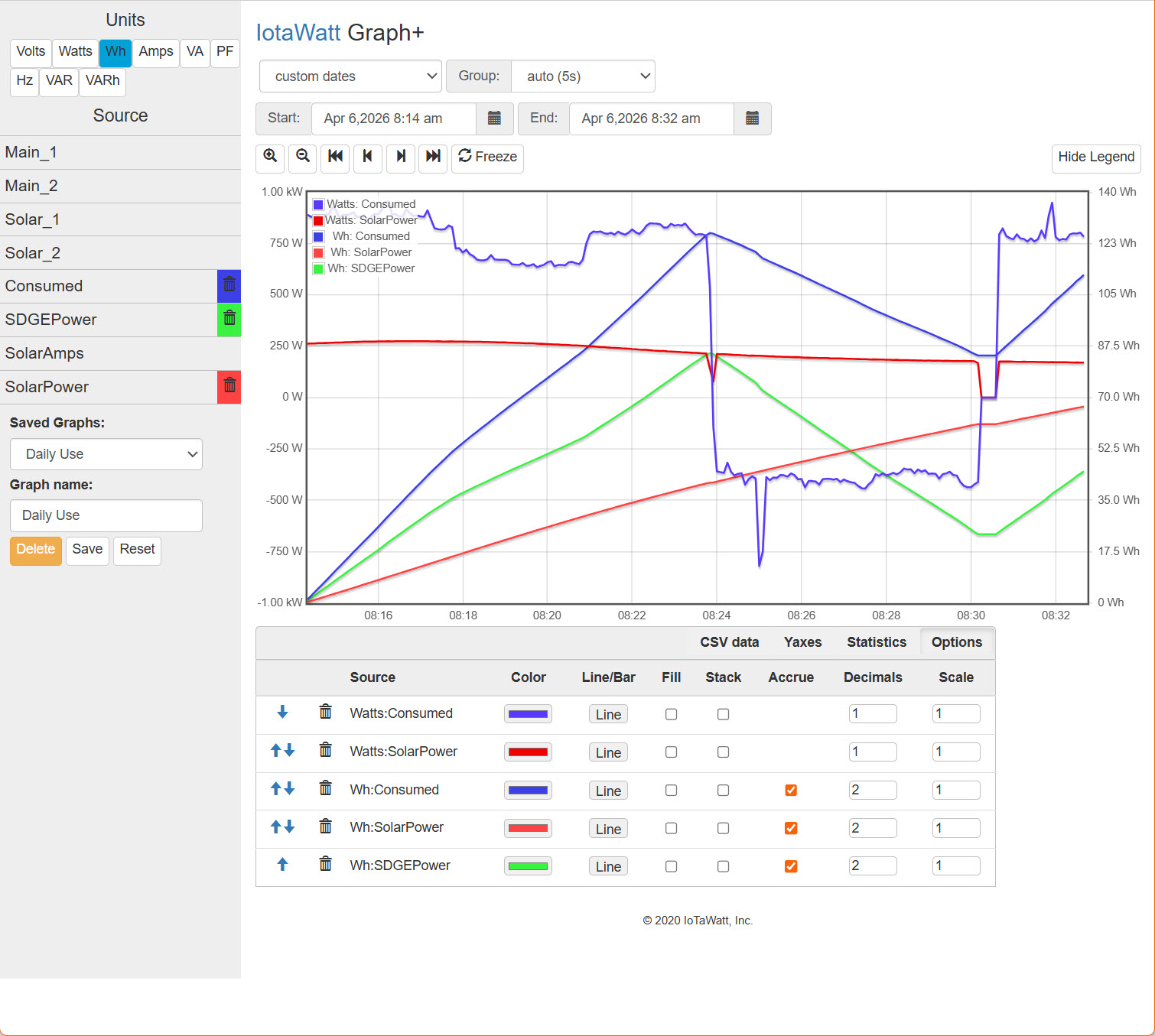
The regular plot I use that shows the watts I am consuming and watts generated by solar. I also integrate those to see if I consumed more than I generated for the day, which typically comes out close to even over the year. After the outage was restored you can see the abnormal consumption wattage of over 5KW. After I reversed the mains the reading was back to normal.
I’m wondering since the 5V USB supply is on a UPS did the IoTaWatt restart? Please post the message log for that period.
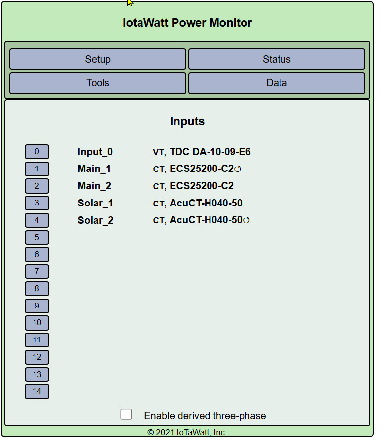
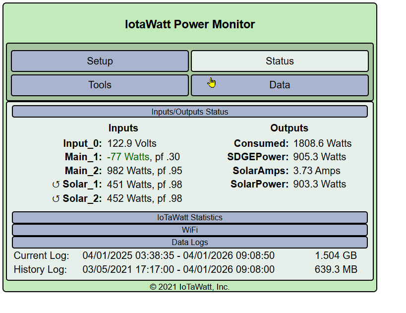
Your Inputs screenshot (I assume all of the screenshots were taken on April 1 after the event) shows only Main_1 reversed.
Was Main_2 previously reversed and now is not?
Did you changed the “allow negative values” setting on either Main input?
I see that at the time of the Status display, Main_1 was -77 Watts with a pf of .30. That doesn’t look normal to me. I suppose its possible, but begs scrutiny.
Re “was Main_2 previously reversed” the answer is yes. When I set it up 5 years ago, I may have had one of the CTs reversed on the wires in the meter box, so I reversed the CT setting for Main_2. Then to fix the issue 4 days ago I reversed the polarity setting for both mains, since the signal seemed to have flipped polarity. The “allow negative values” setting was turned on when I initially set this up 5 years ago and it was not changed recently.
Re very low pf of .30. When the mains usage is negative, that means I am pushing power back onto the grid. So would the pf reflect whatever load the grid is experiencing at the time, since I am not using any main power? I just checked it now and once in while I again see very low pf reading for a short time, but mostly it varies between .76 and .98.
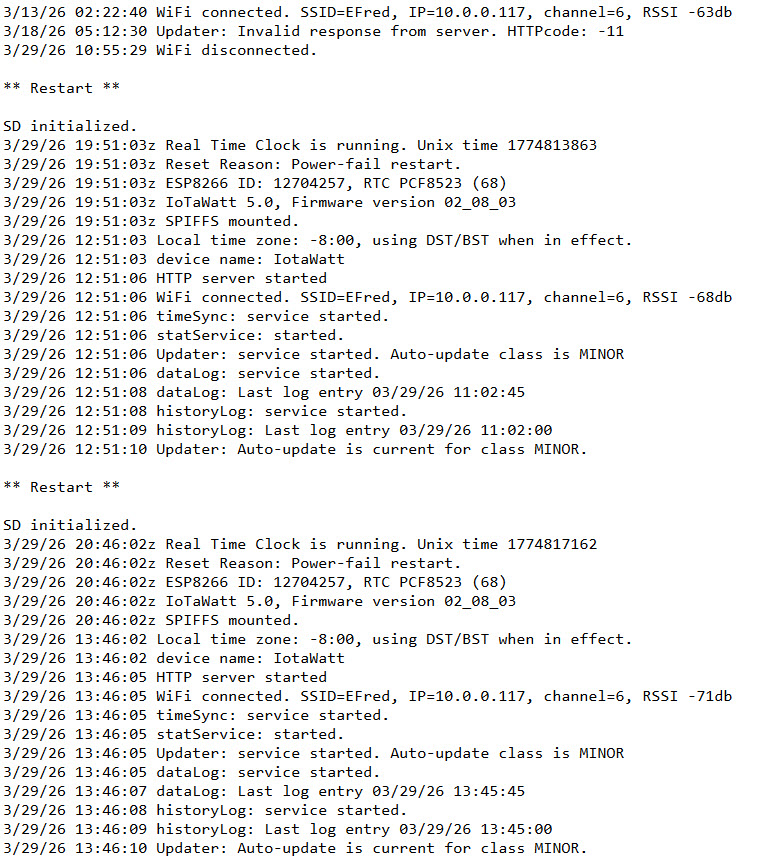
Re “did the IoTaWatt restart?” – Yes it did, twice, due to my actions! When the outage occurred, I tried to look at the IoTaWatt graph, but my computer couldn’t connect to the device even though my main router was also on a different UPS. I forgot that the mesh router closest to the IoTaWatt did not have a UPS, so it shut down and the IoTaWatt disconnected from my internet. But before I remembered that, I tried unplugging the device and restarting it, to no avail. Then after power was restored, the device still did not connect to the internet so I restarted it again. Next time I’ll leave well enough alone to see if it comes back on. I attached a screenshot of the message log.
Note: somehow in the screenshot I sent you of my normal graph output from the IoTaWatt, I had accidentally turned off the “accrue” button for the Wh:Consumed plot. I have attached a new version of that graph for 3/29/26 to replace the previous one.
Hope this helps. But at this point the issue has become more of a science experiment of what phenomenon made the polarity switch rather than how do I fix this (since flipping the polarity corrected the issue). But I appreciate your interest. I guess you haven’t seen this happen before? And there were no updates to the firmware that would have been activated by restarting the device?
Yes, it disconnected at 10:55:29, but was still running on the UPS.
Looks like you shut it down at 11:02:45.
Looks like that happened at 12:51:06. The log shows that it did connect to WiFi, but although the message log shows that the datalog was active from that time, there was no usage data recorded. One possible cause of that might be that the VT was not plugged in, which would also inhibit the web server from responding and make it appear that it was not connected to WiFi. The led state should have been dull green, it would have been dull red if not connected to WiFi.
It was again restarted at 13:46:05, connected again normally to WiFi, and began logging usage.
I can ponder two possibilities to explain the reversed mains:
You unplugged the VT sometime between 10:55 and 13:46 and when you plugged it back in it was reversed from what it was before the power outage. CTs don’t just change polarity. They have no magnetic predisposition. The cores are just iron with no static magnetization.
You reversed the inputs 1 and 2 (Mains CTs) where they connect to the IoTaWatt. That would be obvious upon closer examination of your data because there would no doubt be some identifiable 120V load that would have switched from one main to the other. I don’t think that will turn out to be the case.
Well, I think you solved what caused the watts reversal on the Mains!! It was my fault!
As you mentioned, the only thing I might have changed was reversing the AC plug for the transformer for the VT connection. Basic trouble shooting: “what is the last thing you changed before the problem?”
So I just tested reversing the VT plug again and it did make the polarity of watts change for the Watts:Consumed. I have attached a plot I made just now showing when I reversed the plug and again when I reversed it back. The consumed watts goes negative then back positive.
What I didn’t understand is why only the Mains signal is reversed and not the solar as I think the VT signal is used to calculate watts for both. Then I looked at my setup and found that while “allow negative power values” is checked for the Mains, it is NOT checked for Solar.
So all appears is good and the reason for issue was discovered. Thanks for sticking with me as we worked through this!
Charlie, you may want to check “Allow negative power values” for Solar too. I found out that my 5kW system of 18 micro-inverters puts approximately a 10W load on the system all night when it’s not producing. With your single inverter YMMV of course.