CT Sizing for 100 Amp & 60 Amp Sub-panels and Grouping multiple CT's

I’ve been re-reading the CT Basics and I am getting the feeling that I’ve been doing it all wrong.

The total wattage on my Main_1 and Main_2 have never quite added up and I believe that I have been using the incorrect CT’s for both sub-panels as well as incorrectly grouping multiple CT’s.

I live in the US and have a 150 Amp main panel in the basement with a 100 Amp subpanel adjacent to it and a 60 Amp sub-panel in the garage.

The 100 Amp sub-panel is being fed by a Square D by Schneider Electric QO2100CP QO 100-Amp Two-Pole Circuit Breaker

The 60 Amp sub-panel is being fed by a Square D by Schneider Electric QO260CP QO 60 Amp Two-Pole Circuit Breaker

According to CT basics, each sub-panel is a 120/240V circuit, and the two legs must be measured individually. The wires are too thick to pass both through one individual CT in a U shape, so I put one CT on each wire, BUT - and here is where I believe I went wrong - I used 50A CT’s on each wire had one wire K -->L and the other L <–K. See below for how I have the CT’s hooked up. (my phone broke today so I had to resort to drawing on paper):

Since the breaker is the source and the sub-panel is the loan, I assume I need to make sure both wires are K -->L where L is pointing towards the sub-panel?

The next question I have is regarding the sizing of the CT’s. In the CT Basics, I read: Two individual CTs can also be combined with a common headphone splitter and fed into a single IotaWatt input. When combining this way, both CTs must be the same model with an individual capacity sufficient to measure the combined capacity of the two circuit breakers. (emphasis mine)

Does this mean that each CT individually must be greater than the circuit breaker size, or that both CT’s combined must be greater than the circuit breaker.

So, for the 60 amp sub-panel circuit breaker, each CT is rated for 50A. Do I need to go up to a 100A CT, or do I go by the combined CT rating (50A *2 = 100A) and therefore I am sized correctly on the 60 amp sub-panel circuit breaker?

Same question for the 100 amp sub-panel circuit breaker. Are the two 50A CT’s enough or am I essentially undersized by 50%?

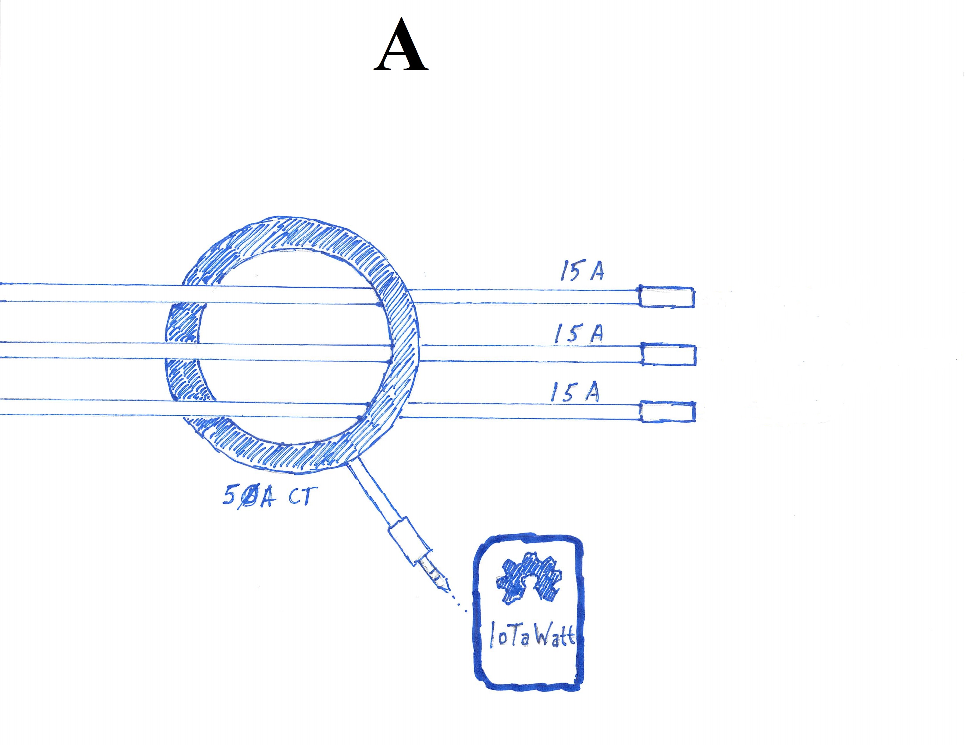
Finally, and last question: when combining multiple wires, can I wrap a single CT around multiple wires (see below):

Or do I have to use exactly one CT per wire then combine via a 3.5mm Y-splitter (see below):

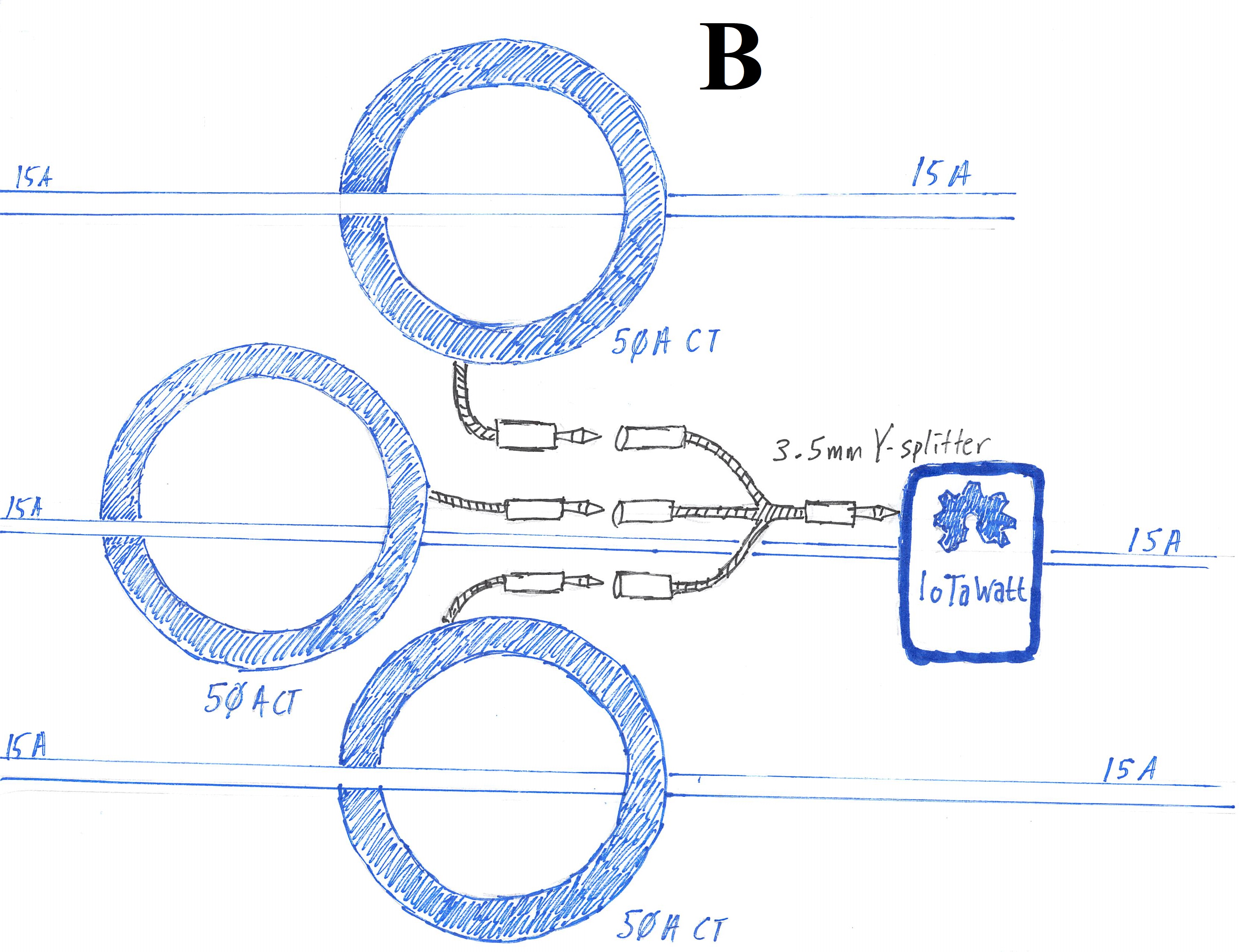
If I do have to use 3 separate CT’s to combine, say, 3 20Amp circuit breakers, do I need to move up to a 100Amp CT? Or will one 50 Amp CT be sufficient?

Appreciate any help!

Nice sketches, but I’m missing some key details:

Are you combining the two sub-panel mains CTs into one input with a splitter, or are you using two inputs? That will effect the sizing of the CTs. If combined, the 100A sub-panel should have 200A CTs and the 60A should have 100A CTs.

As far as orientation goes, your sketch indicates the correct orientation for both sub-panels.

The K->L is a relative indicator and depends on the orientation of your VT, which for North America and Europe is reversible as the plugs are not polarized. So the K->L is used more as a way to install CTs tha same direction or opposite, as the case may be.

Rather than view the sub-panels as mains loads, consider them as any ordinary three-wire 240 load on the main panel. Your 120V voltage-reference is taken from one of the phases, so CTs on circuits using that phase are in phase with the voltage reference. When you are putting 2 CTs on a 240V load, there are two circuits. One of them is in phase with the voltage reference, and the other is 180° out of phase with the voltage reference, so must be reversed. That’s the same reason why you reverse one of the conductors when using just one CT on a 240V three-wire load.

That’s fine, as long as the total doesn’t exceed 50A. But one caveat: All of those conductors must be on the same phase, if any of them are from the other phase, they must be reversed through the CT. Clamp the CT on each one individually. If they show as reversed (little ↺ ), then you need to pass that one through the other way.

You can do this as well, but same caveat with respect to phase, you must reverse the orientation of CTs on circuits of the other phase. One simple way to check this is to plug each of the CTs, one at a time, into the IoTaWatt individually. If the power shows as reversed (little ↺ on the left in the status display), then you must reverse it on the wire. When they all are correct phase, you can combine with the splitter.

I am combining the two sub-panel mains CTs into one input with a splitter. Looks like I need to buy two 100A CTs and two 200A CTs. I am curious how this has affected my readings on the subpanel.

Okay, that makes sense and I believe that is why I initially wired one CT K -->L and the other L<—K because I read in the CT basics section: The phase of the current in each conductor is exactly opposite the other, so they will cancel each other out. Rather than get the sum of the two, you get the difference between the two.

Okay, that’s good to know. I have wires grouped together via 4 CTs going into input #6.
50A CT1: 20A, 20A
50A CT2: 15A, 15A
50A CT3: 20A, 15A
50A CT4: 15A, 20A, 20A, 20A

These CTs add up to 180A . And, because I chose to combine all the CTs into one input, to stick to this configuration, I would need to use 200A CTs? Is the other alternative to monitor less data?

You can look at that with Graph+. Plot the main over a typical day and look for large spikes. Zoom in on those spikes (You can just highlight the graph section with your mouse) and see if the spikes plateau at around 60A for the 50A CTs and 110A for the 100A CTs. It’s entirely possible that your actual usage never exceeds the capacity of your CTs.

If the total actual Amps exceeds about 60A, then you would need to upgrade. You can look at that as in the axample about mains. If it does exceed 60A, it probably will not exceed 100A (actually about 116A), then you would need to change to 100A CTs, or…

If you have a little electronic technician skills, you could use the same 50A CTs but halve the burden resistor and configure as an Accu Energy 100A CT. But first, look at your data and see if it is plateauing.

I did a history from June 1, 2021 - present. It looks like I am in the clear. In that time the main panel has not exceeded 4,000 watts or 32.5 amps. So perhaps I can get away with these undersized CTs.

So it is my understanding it is ok to size CTs based on the actual amps and not what the circuit breaker is rated at.

That sounds low. Remember that when you look at 3 months, you get 4 hour averages. When I do that for my mains, I show peaks around 26A. When I zoom down to 5 second levels, I see those peaks have some 5 second peaks of 100A. So you need to be sure you have looked at worst cases.

Based on actual amps and a good worst case analysis leaving a reasonable safety margin. And then using practical data, like if you have a dryer, heatpump, and water heater, EV charger or other large appliance, what do they all add up to, and what is your other circuit baseload?