Custom 200A CT's

I’m looking to buy a pair of IotaWatts and some CT’s for my panel. I’ve got 7 240V circuits, and 15 120V circuits.

My big problem is getting something on the mains. It’s really tight - mainly because there is a pair of doughnut CT’s already there, from a system installed back in the 90’s. I’ve got no idea of the specs on them, but they’re obviously current-mode (burden resistors are on the 90’s electronics) and likely totally unprotected. Removing them requires disconnecting wires that I’m uncomfortable handling live, or calling the utility to have them pull the meter so I can disconnect / reconnect safely.

The question is, what’s the likelihood that I could reuse these CT’s? I can measure the voltage across the existing burden resistor to get an idea of whether they’re in the right range, but turns, phase, etc. aren’t likely to be easily determined. Any thoughts?

1 Like

A picture is worth a thousand words.

Hopefully it won’t come to that. For obvious reasons I can’t recommend that you do anything with your mains. Even if you have the utility pull the meter, they probably won’t put it back without an inspected permit or a licensed electrician to vouch for the work. Disconnecting your mains and reconnecting can be tricky, especially if you have aluminum wires.

Slim. Would probably involve changing the burden resistors in the IoTaWatt and/or adding external resistors to effectively do the same. Do you know if these CTs are working now?

You would need a good true RMS voltmeter and a good clamp on RMS current meter, and know how to use them.

So post a picture so I can see the layout. I still have a few ECS25200 clamp on CTs that you might be able to get in there.

I’ll get a picture tomorrow. The CT’s do appear to work - they’re driving a 1990 era LED display in the kitchen that I can make tell me the current power consumption of the house, which appears to be reasonably accurate. At one point, I considered just reverse-engineering the comm link (running on 4-wire telephone cable) between the display panel and the controller at the panel, but that would only get me overall power, not individual circuit power.

I was actually considering calling the utility to remove the meter as an option; but I’m guessing that you’re precisely right about them wanting a sign-off before they’ll reinstall. I’m not ready to go down that route.

I can borrow a good true RMS voltmeter and a good clamp on RMS current meter - I’ve got a friend who’s an engineer for Fluke and has lots of good toys available to him. Of course, I run into the same problem - no place to get a clamp-on ammeter into the panel, and no desire to take things apart to get the CT’s out of the panel.

One completely different question, if you have a moment - why use a 120V transformer to get the voltage waveform rather than a 240V one? You’re only seeing the voltage on one leg to neutral; is the assumption that second leg voltage will be (within system accuracies) the same as the first leg?

That’s the next step.

The short and practical answer is that most folks have a 120V plug available near their panel and a decent UL approved 120V wall-wart is readily available. The voltage on the individual legs does move around with load, depending on the resistance of the service cables. But the voltage across the neutral is a function of current, and if the panel is reasonably balanced, the current on the neutral is small, so the voltage across it is small. The hot leads carry all of the current, but then both the 240V and 120V transformers will pick up the voltage drop there.

It’s six-of-one half-dozen-of-the-other. I’ve monitored my split phase panel with two 120V transformers, and for the most part, they go up and down in sync. By far the greatest variations are caused by the collective use of the 4 houses connected to my transformer, and it affects both legs pretty much the same.

A few days late, but I got a couple of pictures if you’ve got a moment. Panel_Small


The first picture shows the external view of the box, note the small attached box in the upper right that holds the ancient monitor, and where I plan on installing the Iotawatt. The second picture is the inside of the panel, and the last is the wiring inside. Note the two donut CT’s installed on the mains, and that there’s about a 1.5" space there - and the current CTs are tightly wedged in there (it’s difficult to move them).

That’s why I was asking about using what’s already there…

Is the small box on the right made of metal? If so, the IoTaWatt May have a very hard time receiving a WiFi signal. You may want to consider replacing it with a plastic box. Also, where are you planning on getting power for the two IoTaWatt transformers?

Interesting… it looks as if there might be enough room for some clamp type CTs if those doughnuts weren’t there, but they are. Just curious what country you are in. I’ve never seen a panel like that in the US.

So let’s investigate those existing CTs. The first thing I’d try to do is identify the equipment they are connected to and try to find some documentation on it. That might reveal the specs of the CT.

Another approach, as I mentioned above, would be to observe or measure the burden value, then measure the voltage across it with a known current on primary. You say you can get a good voltmeter and clamp on ammeter. That you can’t clamp onto the main isn’t a problem, you can turn everything off except that EV charger and then plug in your car and measure the cable on the EV breaker.

If the CT turns is viable, I wouldn’t worry too much about the phase shift. Solid core CTs characteristically have very low shift, and it would be possible to measure it with the IoTaWatt if you have a good high power factor load. Maybe the EV charger.

Location is Phoenix, AZ, which generally qualifies as the USA.

ogiewon -
Good point - I was originally planning on using a Brultech and planned on just running Ethernet into the box. Switching over to the Iotawatt, I forgot that WiFi doesn’t penetrate Faraday cages very well. I’ll have to mull over getting WiFi into the box, because I’m a big fan of air gaps between my network and 240V, especially during thunderstorm season.

OverEasy -
I can get 120V on the backside of the panel inside the garage - there’s a convenient 4-position outlet right there. As far as the equipment in the box, it’s a Demand Controller built by Dencor, and appears to be a solid, high-quality design. The best documentation I can find on it is this patent:

It’s intention was to monitor maximum demand (maximum kW averaged over an hour), and shut down some loads (Hot water heater, A/C, etc) if the house was taking too much power. This was used in conjunction with a demand-based electric rate to reduce cost. Unfortunately, due to its age, there’s not much information on line. I can read the part number on the CT’s - but it’s a Dencor part number, and Google pulls a blank on it.
The next time I get a chance, I’ll pull the guts out of the box and figure out the burden resistor, and see if I can correlate voltage across it with kW. I’ll try with a couple of loads - the water heater or Jacuzzi heater are always good ones (continuous, resistive load), the EV charger is probably a good one at higher power, maybe I’ll try to max out the current (turn on everything) and see what I get.

1 Like

Just wondering if you have access to the cavity below the meter and if the mains cables are exposed there.

Well, that’s a remarkably insightful question. I can’t get into the small panel that the meter is on without breaking the seal, but there’s a big panel below it that I CAN get into. It’ll be before the meter and have the feeders coming from the transformer - but they’d be perfect for a clamp-on meter to characterize the existing CTs. I’m pretty sure the electric company wouldn’t be happy about me putting permanent CT’s there, but it might be a case of “what they don’t know won’t hurt them”. Thinking about it, I’m also not sure what’s in the lower panel on the right - I’m guessing some of the circuits exit the panel there, but it’s likely mostly empty.

I guess I know what I’ll be doing tomorrow…

My favorite is “it’s easier to beg forgiveness than to ask for permission”. If you can get into that lower box and it has the mains exposed individually, I’d just clamp on a couple of CTs and button it up.

1 Like

Well, I pulled the trigger and bought a couple of Iotawatt’s to tame this monster, and pulled out the ancient electronics.
The existing CT’s on the mains are connected in parallel going into the electronics, and have a 5W 0.5Ohm burden resistor on the board. It looks like it gets warm (but not hot), because it’s slightly discolored relative to the second, unused 5W 0.5 ohm resistor on the board (probably used in a three-phase setup, but not in my house).
I don’t know much about CT’s, but the difference between the resistor in the old electronics and the tiny little 20 ohm SMT resistor in the IOTAWatt is…concerning for being able to reuse the existing CT’s. Any thoughts as to whether what I’ve got seems rational?

CSo let’s work backwards. A 5W 0.5 Ohm resistor can handle 3.16A. If the two CTs are in parallel, assuming they are in phase, that would be roughly 1.5 A each.

The first thing to know is that you cannot disconnect these CTs while your mains are switched on. That will probably destroy them. I see that you got two 200 Amp CTs with the IoTaWatt, so is there a plan to connect them to the mains somewhere, perhaps in the lower box as previously discussed?

If so, then the disposition of the old CTs is academic. If you still have it in mind to try to use them, you could do an experiment with the IoTaWatt and one of the ECS16100 that you bought.

You could clamp the ECS16100 around one of the leads on the existing CT, configure it in the IoTaWatt and let it record for @ few hours, preferably while some larger loads kick in. Then graph the results and post it. It will show pretty low power, but I can work that backwards to se3 if my hunches are in the ballpark.

If you can put the other ECS16100 around a large load that will cycle on and off during this experiment, I’ll be able to get some calibration to primary current as well.

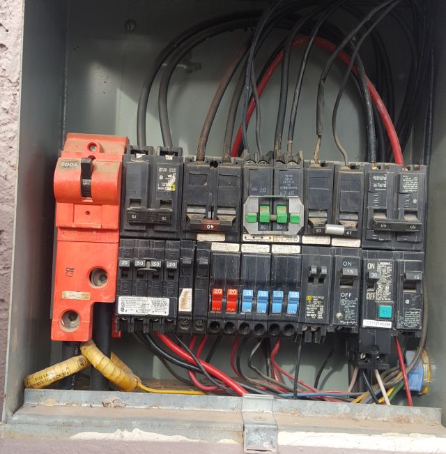
Well, here’s what I’ve got. I shorted the leads of the old CT, and put a 50A ECOL09 on it with the CT lead looped 4 times through the ECOL09 (all with the power off, natch, I’m a chicken).

I have two graphs - one for the loads, and one for the measurement of the CT. No real reason for that, other than I have two IOTAWatts and I hooked the 240V loads up to the first one and the 120V loads up to the second, which is where I stole the ECOL09 from. A whole bunch of extraneous low-power circuits were excluded, because they just made things difficult to read. Iotawatt_a.png shows the loads, and iotawatt_b.png shows the power measurement from the ECOL09 of the old CT around the mains.

So, what I see is:
at around 12:41, there’s a 7550 watt step up in load (green trace, the EV charger), and about 5 minutes later a step down.
Between 12:54 and 13:06, the EV charger cycles between 320 and 1000 watts a number of times.
At about 13:04, the water heater (blue trace) kicks on for about 2 minutes at 4600 watts.
At about 13:17, the A/C and air handler kick down to low speed. A/C drops from about 4550 to about 3380 Watts, and the air handler from about 450 to 165 watts.

On the CT measurement side, we see about a 73W jump corresponding to the 7550W EV Charger turn-on, and about the same on turn-off.
We see about 7W jumps corresponding to the 680W jumps of the EV charger from 12:54 to 13:06.
We see about a 46W jump corresponding to the 4600W Water Heater.
We see about a 15W drop corresponding with the 1450W drop from the A/C dropping to low.

To the casual eye, that might suggest the ECOL09 is measuring about (1/100 / 4 turns through the ECOL09)=1/400th the power drawn by the loads. The ECOL09 is NOT configured with “Double” in the input configuration dialog, so we should probably double (halve?) this estimate to 1/200th the power. Does this suggest that the old CT’s have a 200:1 turns ratio, and I should expect 1A output for a 200A mains current?
Let’s go back to the 0.5 ohm, 5W resistor in the old device. 1A through it would dissipate about 0.5W (from P=I2R) - but there were two CT’s hooked up to the resistor in parallel, suggesting a 1W max power dissipation. A 5W resistor would be a conservative and reasonable choice.

Anyway, any thoughts you have would be interesting to me. I’ve got both IOTAWatts installed, and they’re working great although I don’t have the mains monitored yet or the data getting saved anywhere.

Very resourceful. Good call to make several turns around the CT. Still, the secondary traces are nowhere near as crisp as the traces in the top graph where the CTs are used directly. The math looks good however.

Primary: 7500W @ 240V = 31.25A
Secondary 72W @ 120V = 0.6A / 4 = 0.15A

31.25/0.15 = 208

Given that would match up with 200A:1A, nice round numbers, sound good. I’m not 100% positive, because I’m still a little confused about the two IoTaWatt, 240V vs 120V not doubling etc. but we can prove that out directly.

For the next step, can you connect the CT back up to the 0.5 ohm burden, and then attach a lead wire with a 3.5mm jack wired to the tip and sleeve? Plug that into an IoTaWatt input and set the burden value, under the device menu, to the combined value of 0.4878.

Then configure the CT as “generic” with turns of 200 and use 0.1 as a guess for shift. Fire it all up and see how the power tracks directly vs your known loads. If it looks about right, you could consider changing out the 0.5 Ohm resistor for a 1 Ohm 1 Watt external resistor that you can just add to the cord. Another benefit of using an external burden is that you can then unplug the CT while power is on.

That sounds like a good suggestion. I’ll give it a try when I get some time - with CT’s on all the individual circuits, adding CT’s to the main is mostly a way to verify that everything is configured and measuring correctly.

Like double entry bookeeping. Also would come in handy if you get solar and start exporting.

OK, six months later I managed to get back to this.

I soldered a 1 Ohm, 5W resistor (what the local electronics house had, cause the original resistors have gotten lost) across each of the old CTs, and plugged’em into separate ports on my Iotawatt. I configured the CT’s on the Iotawatt as Generic, with 200 turns and a phase lead of 0.1, with a burden resistor of 0.95 ohms, and started monitoring. I had the Iotawatt creating an output that was the sum of all the other CT’s, and the readings were close but a little low on the old CT’s. With a little jiggering, setting the turns to 208 and dropping the burden resistor down to 0.9 ohms, I get about a 1% difference between the power measured by the old CT’s and the sum of all the small CT’s, over a range of power from about 1kw to about 18kw. That’s pretty darned good IMHO. The difference seems to be consistently the old CT’s being high, so maybe a few more minutes will get me closer (though there’s really no need for my purposes).

That got me thinking about the relationship between the burden resistor and the turns ratio on the CT. It seems to me that both have a linear effect on the measurement - if the turns ratio is off by a factor of two, the current through the burden resistor will be off by a factor of two so the measured voltage across the burden will be off by a factor of two so the reported power will be off by a factor of two; likewise if the burden resistor is off by a factor. So, is there a reason to prefer one over the other as a tuning factor?

By the way, I really appreciate your willingness to weigh in on some of my questions so far.

I’ve got data flowing into InfluxDB, and I’m now working on plotting something - anything - in Grafana. I’m far enough in over my head on those two that I’m seriously considering jettisoning them and doing some Python scripting to download the data and present it. I’ll at least be able to understand what’s happening then. The instruction manual is, however, pretty silent on how to get information out of the Iotawatt unless one desires to use one of the three supported DB approaches. Any thoughts on this before I go start sniffing the Ethernet?

Nice to see a plan come together. I wouldn’t have high expectations to match what a directly connected CT would produce, but 1% sounds great for this indirect setup. I think you have the math OK. Lowering the burden spec will increase the power calculation and raising the turns will lower the power calculation. So tweak away. An alternative calibration test might be to compare the amount of change in the new mains measurement with a high load dedicated circuit cycling on and off.

Not a grafana expert but I did figure it out OK after awhile. You could use Emoncms. Also, the new Graph+ just released in Alpha is more useful;, especially if you save a set of graph specifications for what you want to see regularly.

Thanks for the help.

What I really want is for something that will contact me (text, email, whatever) when it looks like my hourly demand is going to be over some predefined limit so I can turn off whatever is on that shouldn’t be, or when certain pre-defined loads (like the pool pump or EV charger) are running during peak hours when they shouldn’t be. Power costs me a lot more during peak hours than off-peak (like a factor of 5), and a slip-up in demand for one hour during a month can easily add $40 to my monthly bill.
It looks like I can get Grafana to do these things, but there’s a lot I need to learn about writing queries to make that happen.