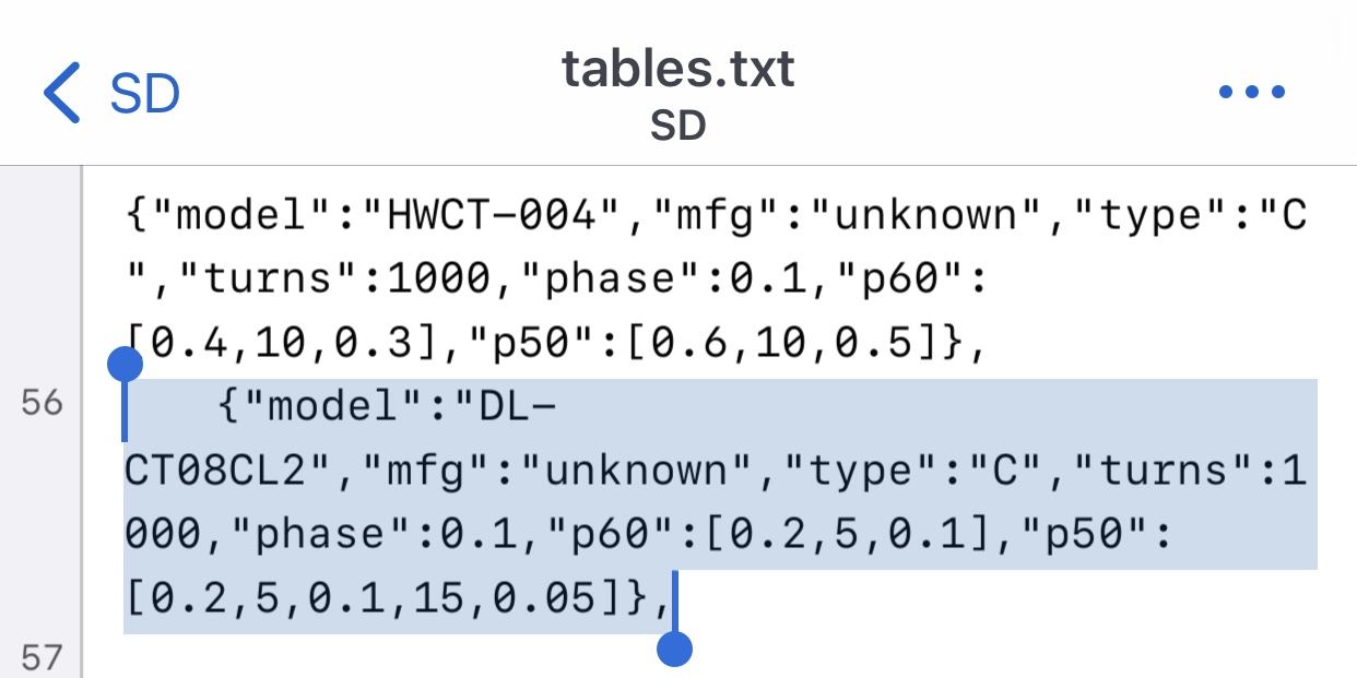
I recall that I am using 1000 turns version. I just follow the value of the tables.txt of the SD card.
If you use 2000:1 version , it will reduce the secondary current by half given the same primary current. Hence, the maximum primary current that can measure will be double.
Alternatively, you can also change the burden resistance to achieve the same effect.
Thanks. I need to find balance between turns/sec current vs burden resistor vs sampling voltage range vs accuracy for my current consumption conditions.
So my IoTaWaTT kit purchaed 10 minutes ago - i wonder how long will it take to deliver it to europe? I took standard shipping as other options are way too expensive for me. DHL cost is much more than all the VTs and CTs i need:P
I made the PCB using DipTrace software. The PCB transformer component is also provided for your reference.
Disclaimer: Working with mains voltage is dangerous. The material provided is for informational purposes only. I take no responsibility for what you do with this material and I am not held responsible for any property or medical damages.
Was that the link to download project files, the one which is dead now? Mine IoTaWatt is working for a year now - i bought original one to see if i;m able to use it:D Looks good. I need to do one more so asking if it is possible to get the files from you and follow your way?
Was that the link to download project files, the one which is dead now? Mine IoTaWatt is working for a year now - i bought original one to see if i;m able to use it:D Looks good. I need to do one more so asking if it is possible to get the files from you and follow your way?