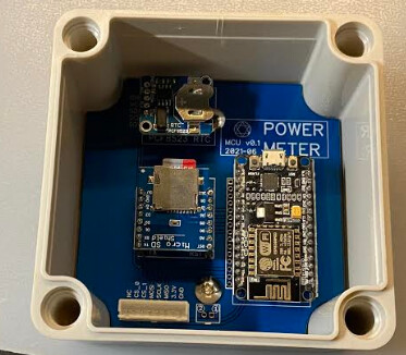
Would like to share my custom-build IotaWatt PCB board.
IotaWatt is too big to fit inside the power distribution box. Therefore, I am trying to build an PCB to replicate the IotaWatt and expose the SPI interface out of the power distribution box.
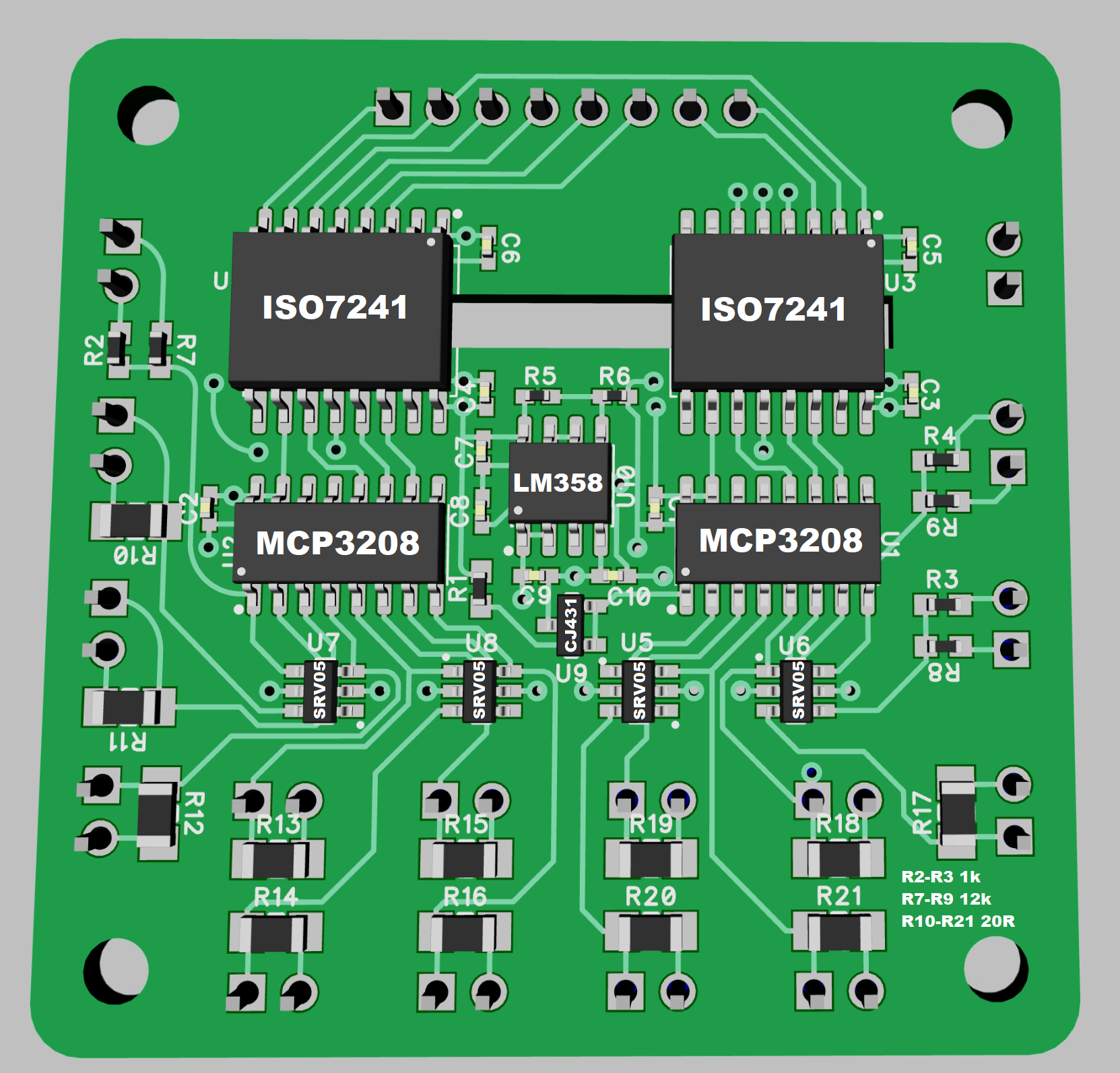
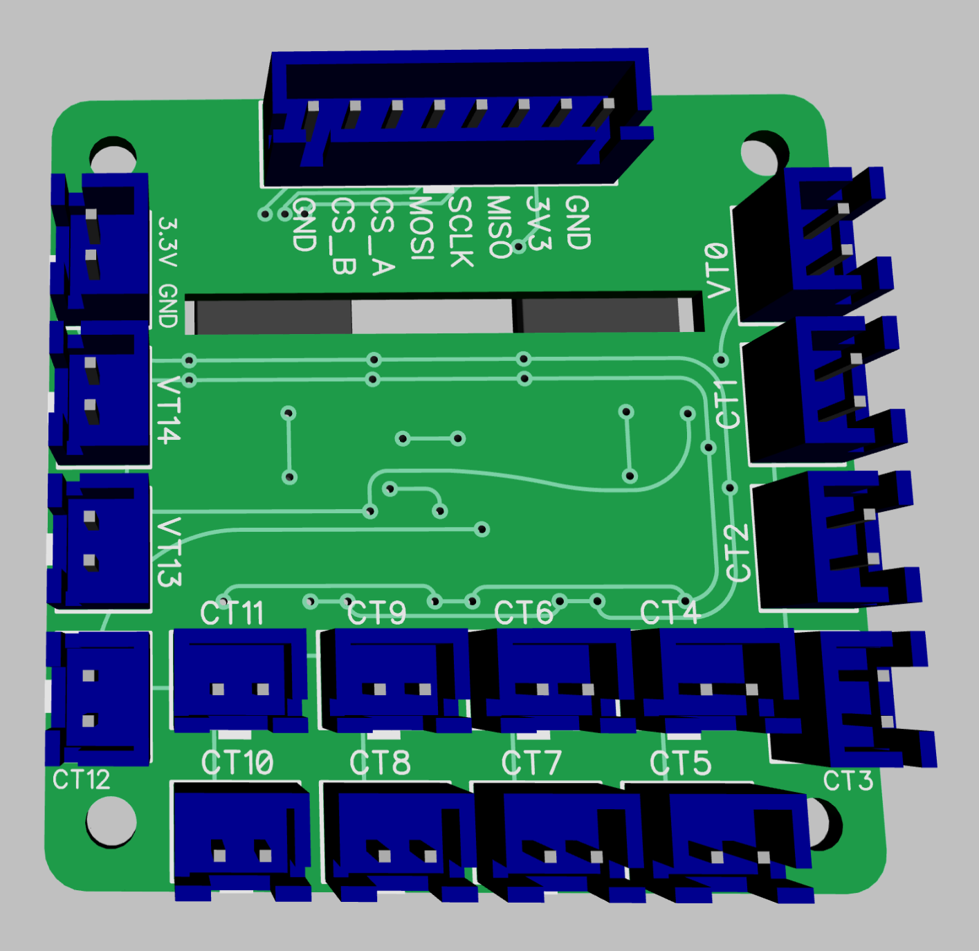
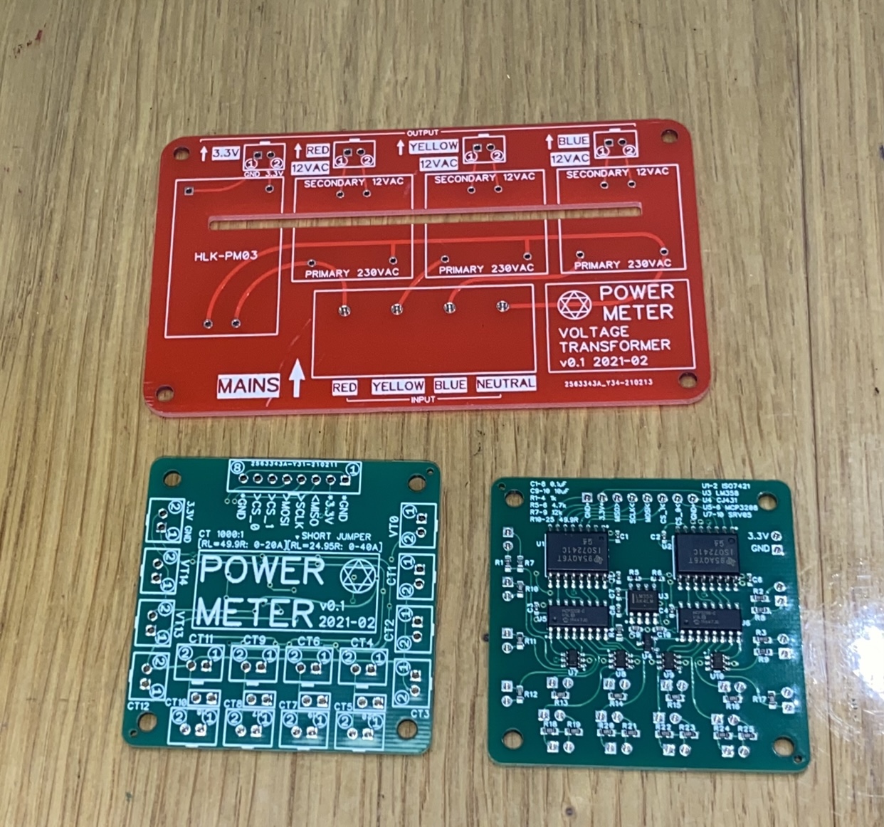
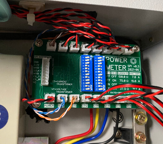
I have added a digital isolator (ISO7241) for interfacing with ESP8266 running out of the box. All the ADC channels are just the same with the IotaWatt, excepted that I modified the port 13 and 14 to “Voltage Transformer ONLY” in order to measure the voltages of 3-phase power.
Should work. Electrically it’s pretty much the same as the extension unit on the ESP32 prototype.
The isolation chips would help with electrical certification, but I don’t see where you get isolation for the 3V3 or GND. The 3V3 could be resolved with another power supply, but that wouldn’t resolve the ground issue. I don’t recommend connecting the IoTaWatt ground to equipment ground.
Curious to see what you are doing for the external head.
The digital isolator has isolated powers and grounds (see ISO7421 Digital Isolator Chip Datasheet). The ESP module outside the box will feed in 3.3V and ground through the upper 8 pin connector.
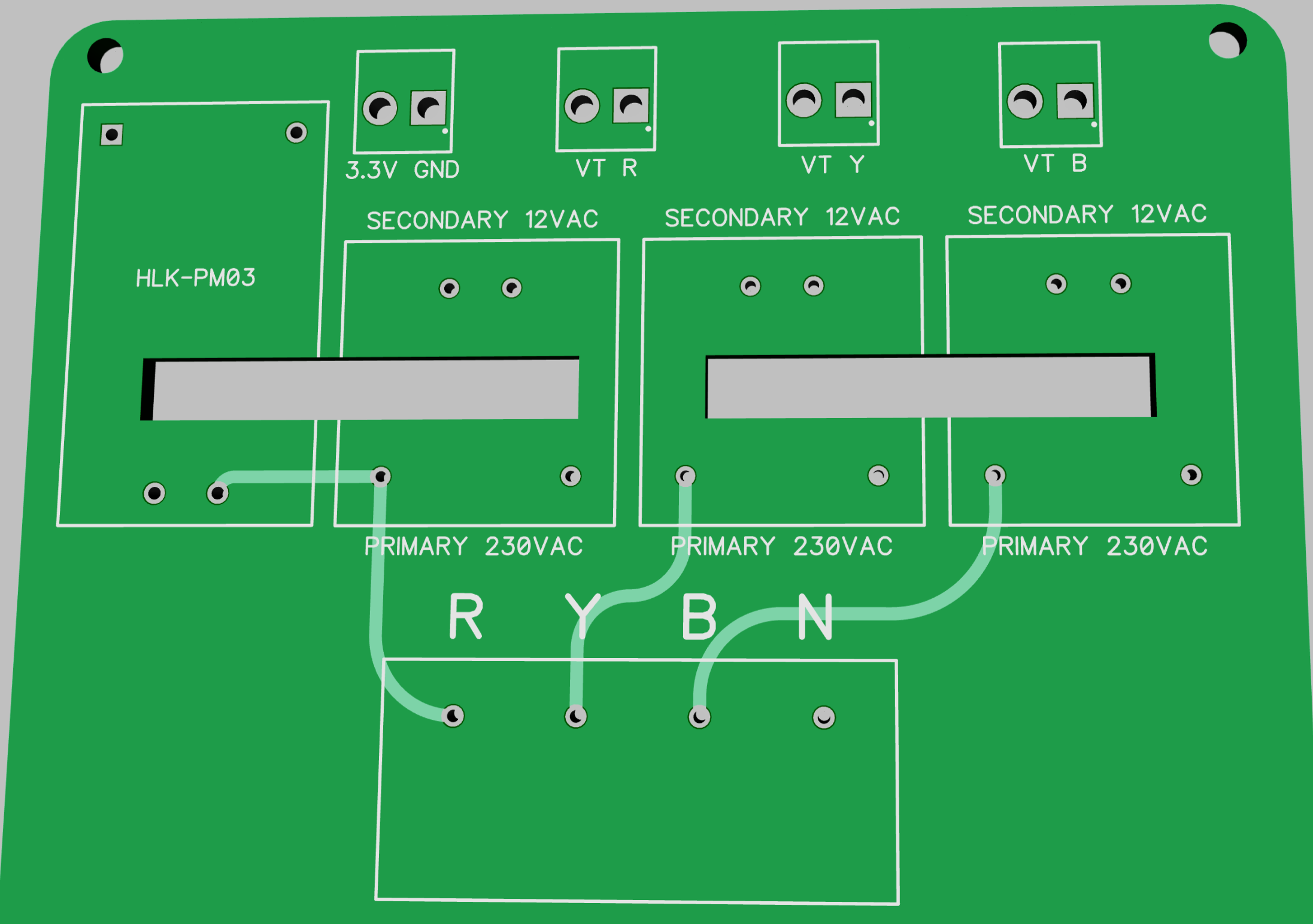
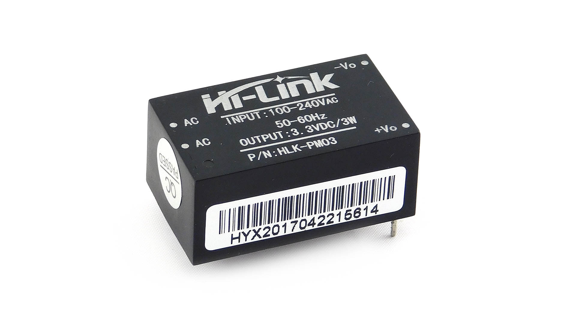
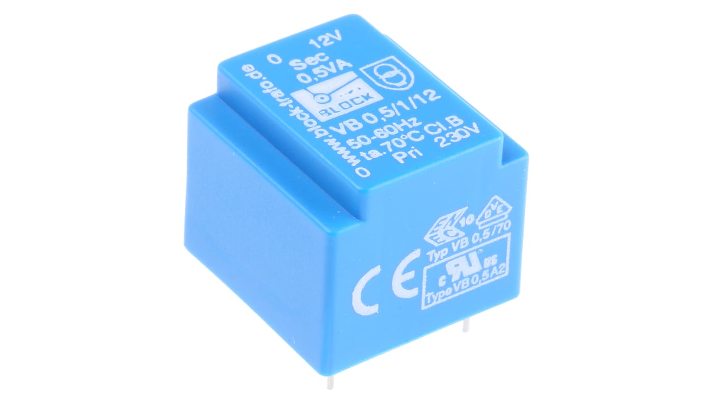
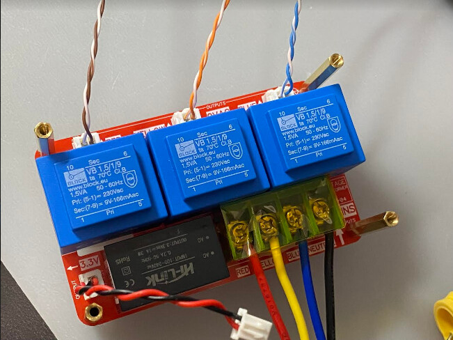
For the rest of the chips, they will be powered by the top-left 2-pin connector from another PCB. This PCB is quite easy to design, and it will contain a 3.3V power supply (HLK-PM03) and three PCB mount hole 12V voltage transformers (Voltage Transformer Datasheet).
Looks interesting, but why not just use a box outside the main panel?
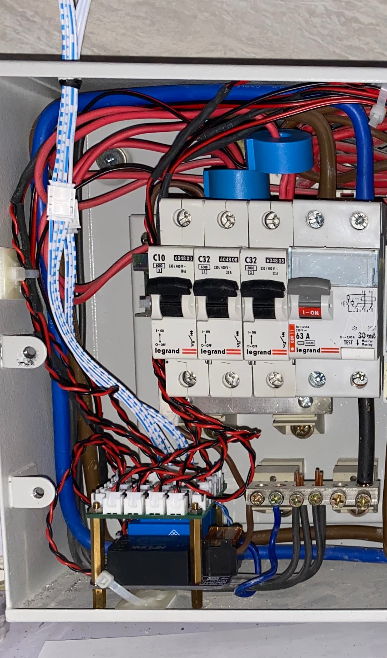
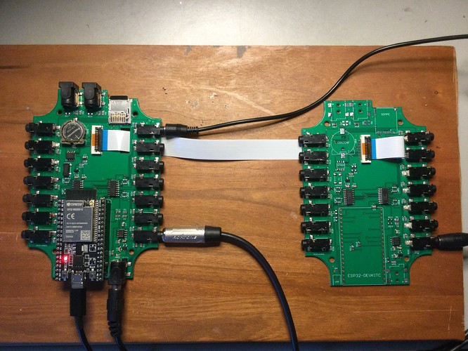
That’s what I did. Only the CTs are in the panel box. They leave via conduit to another box that is big enough for the IotaWatt.
The chip you selected looks fine for isolation, but appears to do nothing to significantly improve the long-distance capability of SPI. I know many people use it over more than a few feet, but it was really designed to be used over much shorter distances. It might work fine, especially for a one-off-home-use device.
Looks interesting, but why not just use a box outside the main panel?
That’s what I did. Only the CTs are in the panel box. They leave via conduit to another box that is big enough for the IotaWatt.
A valid point. Your solution will work fine in my case. The advantage of my design is that only one single cable is need for connection outside the box, so that it is more neat and This design also allows easy changing to a different microcontroller such as ESP32 in the future, without replacing the whole IotaWatt unit.
The chip you selected looks fine for isolation, but appears to do nothing to significantly improve the long-distance capability of SPI. I know many people use it over more than a few feet, but it was really designed to be used over much shorter distances. It might work fine, especially for a one-off-home-use device.
I have to admit that the isolation chip is really not much necessary. The CTs, VTs and power supply are all isolated from mains voltage, and it is not lethal to touch them accidentally. Maybe it is for extra protection.
As a hobbyist, I actually enjoy the progress of making my own PCB.
FYI, I believe the Adafruit huzzah ESP8266 stacked with their datalogger featherwing would have all of the components needed to drive your board. It would be a pretty simple matter to adjust the GPIOs in the firmware to work with that.
Yes, it works pretty well out of the box using the original firmware, except for a small issue for the isolation chip and I had to cut the PCB trace and hard wire it. I think I will remove the isolation chip in my next version as it does not really necessary.
Big credits for @overeasy for creating such great hardware and software. I am just following his design and I think I should purchase an original Iotawatt to support him.
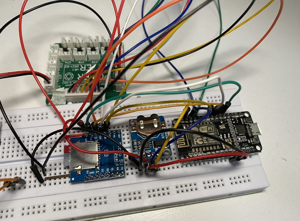
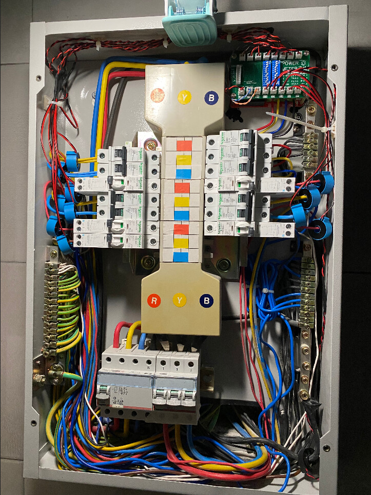
Here is a quick update on my setup of IotaWatt using custom-build PCB. The system has been working flawlessly for a month.
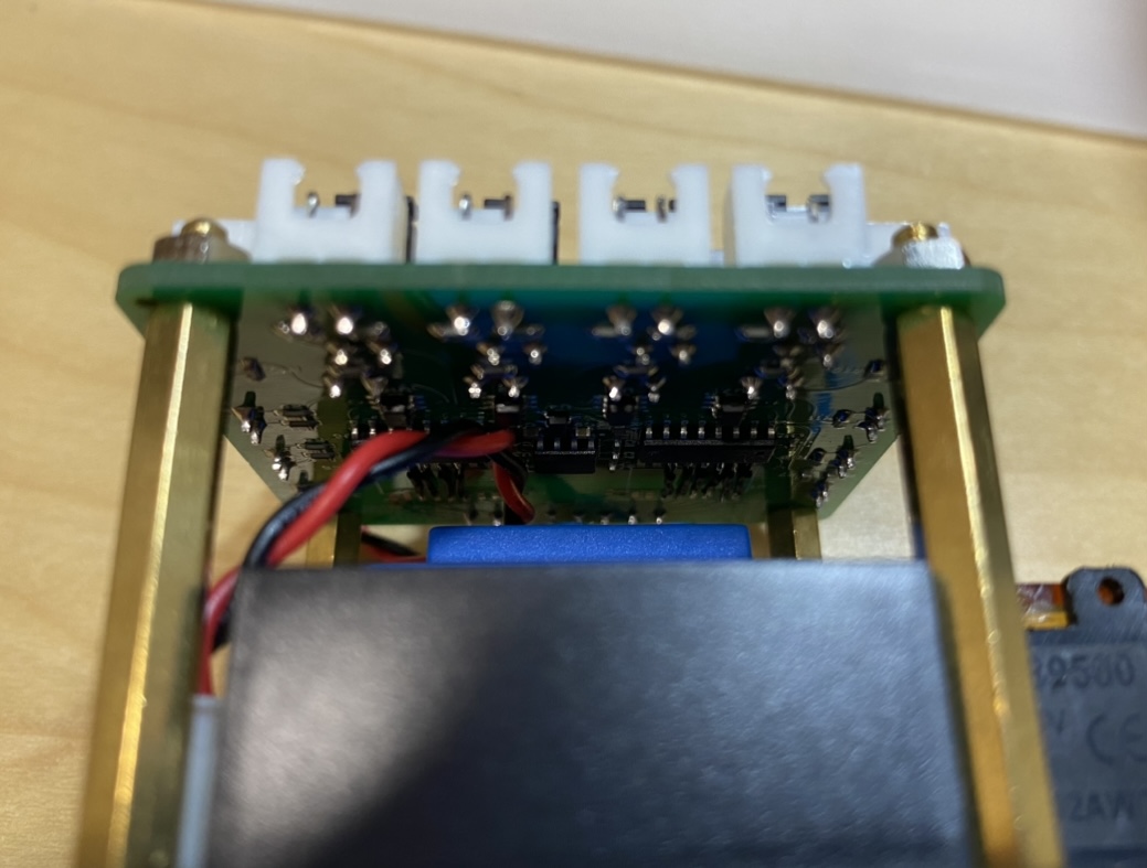
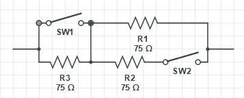
Revisions are made on the PCB. I have added 2 DIP switches to select the burden resistors so that the sensitivity can be maximised depending on the maximum current rating of the channel.
@polyfaces Hey mate, looking to do something similar. Would you be happy to share your board designs? Australian distribution boxes can be quite tight haha I want to future proof for ESP32 connectivity as well as remove the need for the plug packs.
Too late to the thread, but I wanted to add that those isolators are sometimes really painful to make them work right. Try the TI ones… they do not require some of initial patterns…
polyfaces - are you still alive?
Regarding those isolators - in couple of places i’ve seen opinion they are really not necessary. CT and VT are isolators, burden resistors are in place as well, SRV05 diodes are in place. Why additional isolators?
Yes, my custom-built IotaWatt didn’t catch fire, and I am still alive . It has been working flawlessly for a year and two months.
My original thinking for putting isolators were to provide extra protection. However, as you had already said, all those CT, VT, burden resistors, TVS diodes are already good enough. Therefore I didn’t include it my final design.
By the way, I have also setup another custom-built IotaWatt using my original small PCB version. Glad to share some pictures to you guys.
Brilliant. You got it right:) Good there was no fire nor electrocution;P
I can see you’ve made one phase version - or you decided to use one voltage measurement for all 3 phases? I need to make a version with 3 VTs as i found in my place there is significant difference in voltage between phases:( I.e. 249 VAC vs 232 VAC - clearly somebody around is injecting solar power into on phase only:/
The idea is to make IoTaWatt split like yours. I’d like to have a PCB with three VTs and HK power supply. Regarding VT: i’ve found nicely small units, only 0.35VA power, secondary current is 60mA and voltage 9 VAC. Their dimensions are like 21x24x25 mm. Is there any special consideration needed when selecting VT other than secondary voltage in the range of 9-12VAC?
Could tell me what CTs are you using? In my case i can’t use split core CTs as there is no room in my cabinet. Those you show in the photo are looking neat. I’ve seen similar looking CTs on aliexp***.com.
Any change to share PCBs project for reference?
Are you using MQTT at some point in your power monitoring system? I have a test bench system based on RB Pi4 with containers based (Docker) Mosquitto MQTT, Node-Red and Grafana. somehow i can’t see how yo use Home Assistant - it is in IoTstack package but there is some bug so no supervisor mode is available:/
Thanks for sharing your ideas! Aprreciate it.
Bogi
The single phase version is for another house which has only single phase. Also, the electric box is smaller in size.
For VT selection, usually larger is better. Please note that for those PCB through-hole VT, they are usually small in size.
For the CT, I use the DT-CT08CL2 which is already work with IotaWatt out of the box. No calibration is needed.
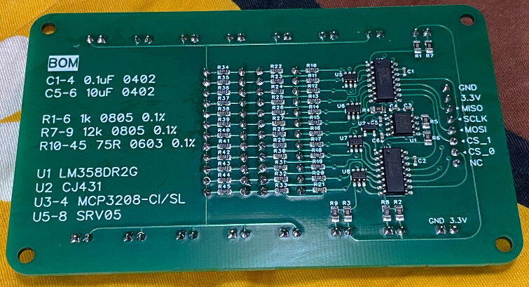
For the PCB, the schematics is very much the same as the official IotaWatt.
For home assistant integration, I did’t use MQTT. I simply configure Home Assistant to make HTTP request every 5 seconds to the unit directly and return the JSON (see HTTP Sensor). I used to use a custom-component of home-assistant created by someone, but it is usually not maintained and got broken during version upgrade
I can see many flavours. Do you know what “CL2”, “CL5”, “CL7”, “CL12” means at the end of DL-CT08? Initially i thought it’s something about accuracy class but i don’t think so now.


 ) would you be willing to share your designs?
 . It has been working flawlessly for a year and two months.