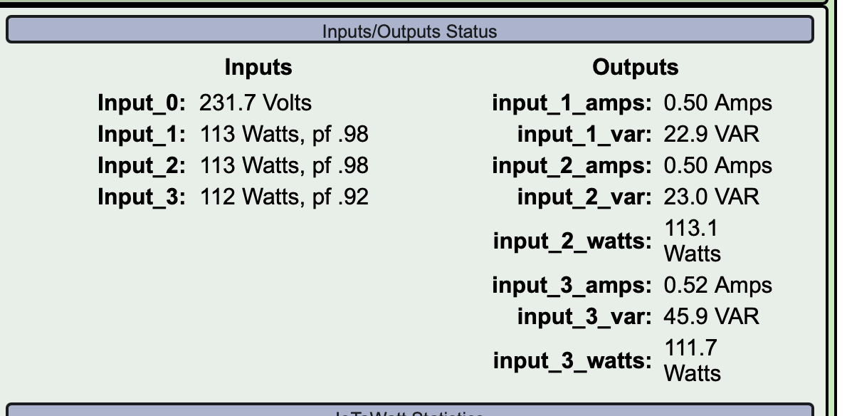
So, have a DYI board. Initial testing showed the readings were quite off (tested with 75w and 100w Incandescent bulbs).
Initially used a very small VT, upon reading I understand that quality matters here. Official supported ones with shipping cost a fortune over here, so though would try out something that local shops have. Went out and bought the heaviest 230->9v they had (open type, weighs 0.9 pounds)
But it does not seem to have improved: 100w reads as 111 and 75 reads as 85.
Voltage calibrated with cheap voltmeter I have and by looking at mains smart meter made for solar - both showed ~ 231-232v
CT used for testing were HWCT-004 (one with very short wire, another with extended about 6 feet) and SCT013
So before I go and splurge on official VT - can there be something else off - like my soldering, PCB quality, esp board, reference shunt (I used LM4040B25FTA which says 0.2%) ?
Ok, so I guess multiple things going on, one of them be not being an electrical engineer.
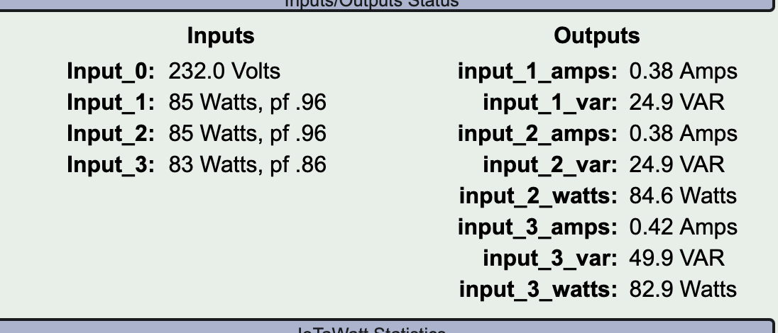
It seems that my power supply is actually not that great. Replacing with simple usb charger and adding two 6.3v 4700u capacitors in parallel reduced the idle amps measured on CT from 0.1 to 0.01-0.02 ( still fluctuates just as var)
I also decided to check how much actual watts is that 75w lightbulb - by leaving that only on and looking at the 250$ mains meter which was installed with solar (so guessing that should be accurate).
Surprise for me - 83w, 0.36A. I guess i need a better multimeter
So with the power supply changed I get 83w in iottawat, PF is 0.99 (still 0.01 short to 1) and amps are off by 0.01. But I guess that’s the best I’ll get
the only thing that still does not align is the vtphase (command?vtphase=1). Description on this forum says it should be negative while mine is positive and fluctuates quite a bit (0.2-0.5)
Ok, little bit more testing. I actually remembered that I had an old 3phase ABB B23 din rail meter which I hooked into my testing ring. Tested with 60w, 75w, 100w rated bulbs and tested by doing a 3d print - though the PF is still a bit off , the wattage and kwh seems to match quite accurately.
Except … the hair dryer  It’s an old Phillips hairdryer that has two speeds and three heat modes (cold/medium/hot). So all is fine and aligned if it is just blowing cold air, or if it is blowing max hot air. Yet in the medium heat setting - Iotawatt seems to be completely off.
ABB: ~548W, PF0.9, 2.6A
Iotawatt: 112W, PF0.44, 1.12A
And the kWh are also off. While for the same period the ABB logged 0.04kWh the Iotawatt logged 0.023kWh
Also the output voltage after shunt seems to jump a bit (at least thats what my cheap tester shows) going between 2.49 and 2.5, while esp supply seems stable at 5v
aaand one more: out of three boards (since I have 3phase install and quite some circuit breakers decided to have one device on each phase) shows high amps on all of inputs even when nothing is connected (16amps when configured as hwct-004). Voltage ref seems to be ok, shunt shows 2.5v and this affects all inputs so not sure - defective esp?
ok, so this one was bad solder joint on LM358. Checked the voltage on the ADC channels and it was ~1.95 when idle, instead of 1.65. Fed that info to ChatGPT and it actually suggested steps what to check. It was insistent that values of R1 and R2 are wrong and should be 10kΩ … but yeah  . Quite interesting AI application to learning electronics. By this tempo I guess I’ll have a full understanding of this schematics by the end of the year.
Also saw that digikey stocks 77DE-12-09 VT (while the 77DE-06-09 is on backorder till end of summer) - could this be used and could the phase shift be similar?
Replaced the power supply to a good one from MeanWell and added couple of low ECR capacitors. So testing with the kettle which does ~1600w actually shows a stable -1.2 on /command?vtphase=3 which allows to configure the VT phase shift as 1.55. That still does not get the bulb PF to 1 (0.9945) and when checking vtphase the numbers are all over the place with 0.17 to 1.1 - so some kind of noise is still present? Bad solder?