As you know, I am using Triad transformers to do VT. What I will do is have one per split phase and one 220V… I know it is not necesary but at the end I will have 5 Iotawatts (3 on one panel, 1 on the main, and 1 on a sub). And well… I just want to be able to measure all voltages and be able to compare between IoTTaWatts and phases…
I see that the calibration for Gain and Phase correction are stored in tables.txt
Is this file overwritten each time an update happens? How can I add my VTs locally without risking to get them deleted?
Any place where I can understand what “phase”, “p60” and “p50” are (I assume generic phase correction that gets applied to 60/50Hz, and specific phase correction for 60 or 50Hz). And what does the array means (used for CTs, but VT only has 1 value).
Yes, and the table can be updated independently between releases as I add new entries. (If auto-update isn’t NONE).
Configure them as “Generic” or send me two to measure and add to the official tables.
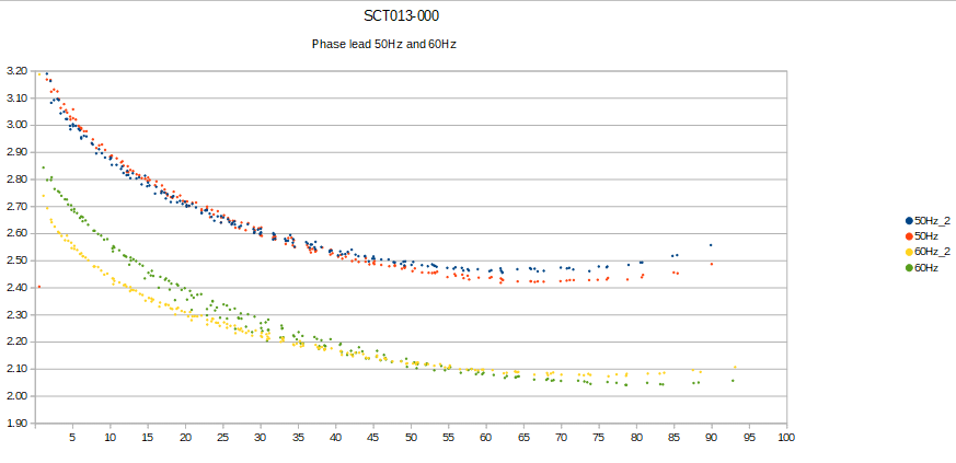
The code. But as you noticed, it’s largely moot for VTs as their phase shift doesn’t vary enough within the working voltage to warrant it. They do vary significantly with frequency however, so the P50 and P60 are useful for 230V/240V models that may be used in both situations such as the Ideal 77DE-06-09.
I have them as generic and I will check the phase and if it is bad enough I will send you the values. I would assume that you measured the input phase and output phase and the value is in degrees? I will send you the measurements once I have them…
As I mentioned in another post, I am almost exclusively a hardware type… I will try to read the code and see if I can get something but it is over 15 years that I have done something in software!
Sorry to say that I keep an inventory of all of the VTs and CTs that I have entered in the tables. So I would need two of the actual VTs to add to the table. This has nothing to do with your ability to measure. It’s about publishing data concerning other products and being able to substantiate or correct that data if disputed.
Its moot. You can’t specify the frequency specific arrays for generic devices, and It’s not useful for VTs. The testing for CTs, where it is important because shift can change significantly with primary current, requires many data points to construct. I built a testing instrument that does measures at various current ranges and at both 50Hz and 60Hz. As with the VTs, I keep at least two samples to substantiate or correct any questions.
Another dimension with the CTs is that phase shift is also a function of the burden value, so if that is changed, additional testing and a table accommodation would be needed, and so I need to retain the samples.
Yes, you are linearizing the phase over load main current. I saw some papers talking about the error induced on power when PF <<1. I am glad to hear you are correcting for that.
And in regards with the burden resistor. I was looking into the datasheet (AcuCT-H040-50) and it appears that the best value for a 50A is 20Ohms. But they recommend other values for other values of current. And I was wondering about that. I would assume that you did the calibration for a 20Ohm burden. And I would also assume that if I change the value of the burden resistor, you do not do any math or self-calibration to correct the response of the CTs.
Going back to the VT’s… are you OK adding 2 new VT’s to your box collection? I am yet to order a new set of transformers and I could easily add two extra to the order… Or I could send you the PNs: TCT3-12E07AE and TCT3-11E07AE
The phase in the transformer will change with load. So in theory, the phase could change as more and more IoTaWatt’s are added in parallel. But the divider is kind of large, so I would expect minimum effect. I will try that as well…
I see that those are chassis mount transformers. I have been listing only wall transformers, but OK. I’d prefer that you add a plug and barrel jack so I don’t need to.
The load is 13K, so load is < 1mA per IoTaWatt.
Couple of notes:
My rule of thumb is that transformer phase shift is generally inversely proportional to weight. at 8 oz I would expect fairly large shift. We’ll see. While IoTaWatt corrects, little correction is better than a lot. Most CTs are in the 1° or less range, so a big VT shift isn’t great. If you are going to share between 5 units, I’d recommend using a heavier wall-wart.
It is critical that you observe polarity with the AC reference in all units, and that you use independent USB power supplies for each of the shared units.
Believe me when I say that little correction is best… but that most instruments you use (scopes, dmms, spectrum analyzers) have heavy corrections applied to the measurements. It means one has to be really careful with noise, resolution, digital resolution (as to not loose significant bits in math for example). But as a general rule, yes… the less the better.
Right now I have independent USB supplies for each IoTaWatt… But I am thinking to make a little board that gets 110V and gets me 4x5V isolated outputs. The idea is to minimize space as much as possible when I have my panel mostly full (42 circuits…)
I will test phase for these transformers before sending anything to you. They are only 2.5VA (instead of 5VA or 10VA of the wall-warts). It should be fine with the number of IoTaWatts but I will test it before anyway.
When I say you need to observe polarity, I mean that the center pin of all the jacks connected to a single transformer must be connected together, and same for the outer barrel. When you share a VT, you are essentially connecting the bias voltage of all of the IoTaWatt together. That’s why they need completely independent DC supplies, so they will not also share a common ground, which causes all of the op-amps to fight each other to set the bias voltage.
If the polarity of the AC reference is reversed with a common ground, they will cook as the AC is shorted through the common ground. I know you want to build something as part of this install, but be very careful. Look at the IoTaWatt schematic. They can be ganged, but they were not designed to do that.
Yes I understand… I checked the schematic…
You could connect them to the same power supply and not having them isolated but it is risky…
What I was thinking of doing is different. Having a 110V to 12V AC-DC power supply (so I can use a UL recognized component). And then having 4 isolated power supplies from 12V to 5V… It is smaller in space than having 4 wall-warts… They would be completely isolated and then I would not need to worry about polarity on VTs (Just pointing this out again in case someone reads the post).
I have samples for both 240V and 120V TRIAD 2.5VA transformers. I could send them to you if you want.
I have not tested them accurately because it is not really easy to do so with the scope. A quick measurement I did was about 4 to 5deg, but I do not trust the measurement that much yet. I will be trying to measure them using the IoTaWatt once its all set up.
I suppose 4° to 5° is possible with such a small transformer, but I suspect it’s not that much. When you have he IoTaWatt setup with those transformers connected, I can show you how to measure pretty accurately using the IoTaWatt and either a known reference transformer or a good quality CT with known shift.
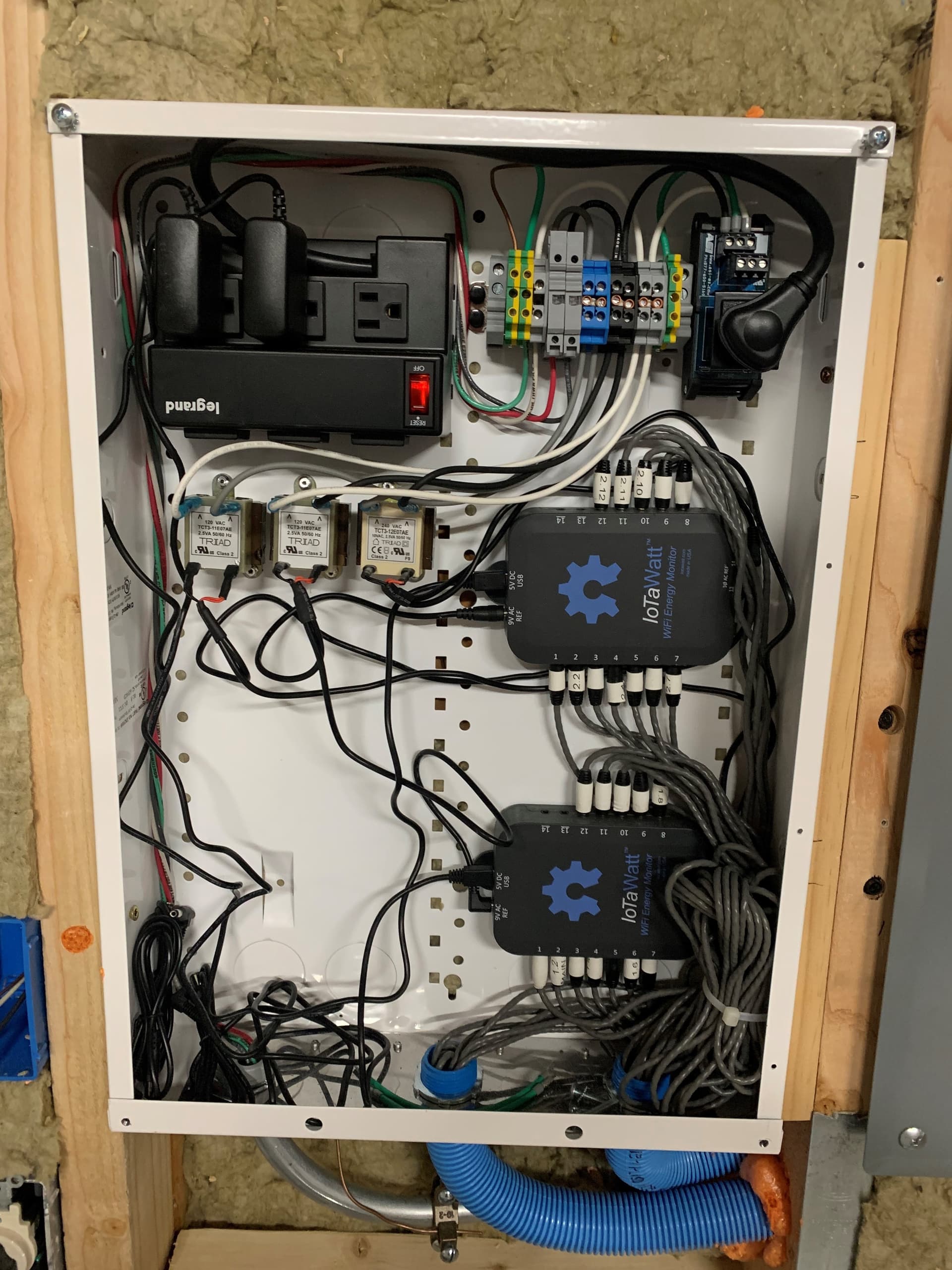
Hello @overeasy, sorry for the long delay. I finally finished installing the two Iotawatts on the inside panel. So I could try your cal method.
A picture for reference:
You will need to compare the shift of your transformer(s) to the shift of a relatively known standard. You can use one of the VTs that are already in the data tables, or you could use an Accu CT or Echun CT installed on a circuit with a moderate purely resistive load. Let me know when you have that available.
Sorry, I sent you a cryptic message last week… I got a heater that is mainly resistive that I can use to calibrate. I also have a circuit with an AccuCT-50 in it and a few extra AccuCT-50’s I could use…