Has anyone tried inputting a DC signal to an IoTaWatt input? What results did you get?
I know Overeasy mentioned making the IoTaWatt more general purpose a couple years ago in the message threads and decided not to do this.
I have a need to plot temperature along with current for my heat pump to help diagnose a problem with it and was considering feeding my IoTaWatt with a 4mA to 20 mA signal from a temperature transmitter. This seems like it should work and I should be able to use the output calculator to make an Amp output that actually shows deg F temperature as Amps then it’s just a quick mental (Amps is actually deg F) conversion.
The only way I can do this right now is to grab a screenshot and drop it into Word and enter temp values retrieved from a historic weather source along the bottom of the screenshot. It’d be much better to be able to plot them together.
It’d be easy to test this but I’m just wondering if anyone else has tried this. If not I may try connecting a dry cell in series with an external 20 ohm resistor then the internal shunt will see about 37.5mA and see what the IoTaWatt shows it as. Configure the input as generic and experiment with the turns ration and the calculator to see if I can get what I need.
Shouldn’t do any harm as long as the input < 50mA. In your experiment, both resistors should see 37.5mA (assuming you are talking about a 1.5V dry cell).
Internally, you will still need to have an AC adapter connected as the IoTaWatt will sample for one AC cycle. Offhand the RMS current should be reasonably accurate. The ESP8266 based IoTaWatt do look for a balanced signal - equal positive and negative current - and use that to adjust the constant used to remove the DC bias. With a steady DC input, that will drift to the limit of the range correction, which is 0.5% or 20 ADC counts. So it will be important to observe polarity of your input and allow for the bias removal drift +/- when calculating the result.
I connected 1.5V drycell (1.6V actual) and a 22 Ohm resistor in series with Input_14 and configured it as a generic CT input with 100 turns. My IoTaWatt is showing 35.2 Amps.
Now to just figure out what I need to do in the output calculator to get 1 A per deg F with a 4 mA to 20 mA temperature transmitter that covers -50 deg C to 50 deg C.
I’ll lose some resolution for only part of the range of the input but it may be good enough.
I seem to be off by an order of magnitude. Are you sure you specified 100 turns?
Basically, the current reported is the current on the burden times the turns ratio. So if I’m right about it being 1000 turns, the current through the burden should be 0.0352A or 35.2mA.
But with the asymmetric signal, the adjustment to the offset of the ADC bias would skew the reading low by 20 ADC counts, which is about 0.8mA. So the actual current should be 36mA
So I just did the same experiment, except that I put my meter in series to read the mA directly. I got 3.20A on the IoTaWatt with turns=100 and 32.8mA on the Fluke meter. So that verifies the 0.8mA constant error due to the asymmetric signal adjustment.
Making progress towards measuring temperature with my IoTaWatt.
I have a -50 to +50 deg C (4mA to 20mA) temperature transmitter and RTD on order which should arrive in another day or two.
First thing was to figure out how may degrees a 0 to 50mA span would represent given that 4 to 20mA (16mA span) was 100 deg C. A 50mA span came out to be 312.5 deg C. I’m going to equate degrees to Amps. 312.5 degrees will be 312.5 amps.
Next task was to calculate how many turns to use for the CT in the input. 312.5A / 0.05A = 6250 turns.
With 12mA being the center of the range I needed a 75 deg offset. With that I setup a new output. I named the output Temperature and used amps with my input. Temperature would then be my input -75.
The 0.8mA offset you mentioned was making my readings about 5 deg low so instead of input - 75 I tried input - 70. Now it’s very close.
Once my temperature transmitter and RTD arrive I’ll redo this as deg F and fine tune it. I’ll report back how it works out.
Looks like you’re making progress. There’s probably more ways to look at the problem. By way of validation, here’s what I came up with:
16mA represents 100C so turns should be 100 / .016 = 6,250. (Should it be 101 / .016)?
.8mA offset correction works out to .0008 x 6250 = 5 deg. low.
the 4mA bias works out to .004 x 6250 = 25 deg.
So the input value is adjusted by +5 (offset correction) -25 (bias removal) -50 (range start) = -70
A word of caution. The sleeves of all IoTaWatt inputs are connected together and to the bias output of an op-amp. The ballast is between the sleeve and tip, and the tip goes to the ADC. Looking at 4-20mA devices, they are powered by an external source, and the 4-20mA leads are probably not isolated from that source. If connecting more than one of these, you could run into trouble with the common sleeves interconnecting them if they are not each powered by an isolated supply.
My RTD, temperature transmitter and loop power supply arrived today. I calibrated the transmitter to the RTD and connected everything. I’m seeing 25 deg C (77 deg F) outside right now and that agrees with the weather service. Looks like this is going to work just fine.
I’ve done as you suggested and wrote this up in the case study section as “Monitoring Temperature with IoTaWatt”.
Below are the components that I use to measure and plot temperature.:
The picture below does not depict the RTD that I used. I got the “waterproof type” RTD which can be completely exposed to moisture including the cable.
I used this power supply because it came with an adapter to easily wire it into my circuit.
Since all the sleeves of the input jacks are wired together in common then if one wants to use more than one 4-20mA transmitter you’d wire the negative side of the supply to the sleeve (only one sleeve is necessary) of a connector, the positive side of the supply would connect to (+) side of each transmitter and the (-) side of the transmitter would connect back to the desired input jack via the tip connection of a 1/8" plug.
Before wiring everything up I examined the output of the 24VDC switching supply with a scope. It had some high frequency noise spikes and hash on it but as it worked out this did not seem to affect the performance. Before connecting it to the IoTaWatt I used my multimeter with an ice bath and a warm water bath and a thermometer to calibrate the transmitter.
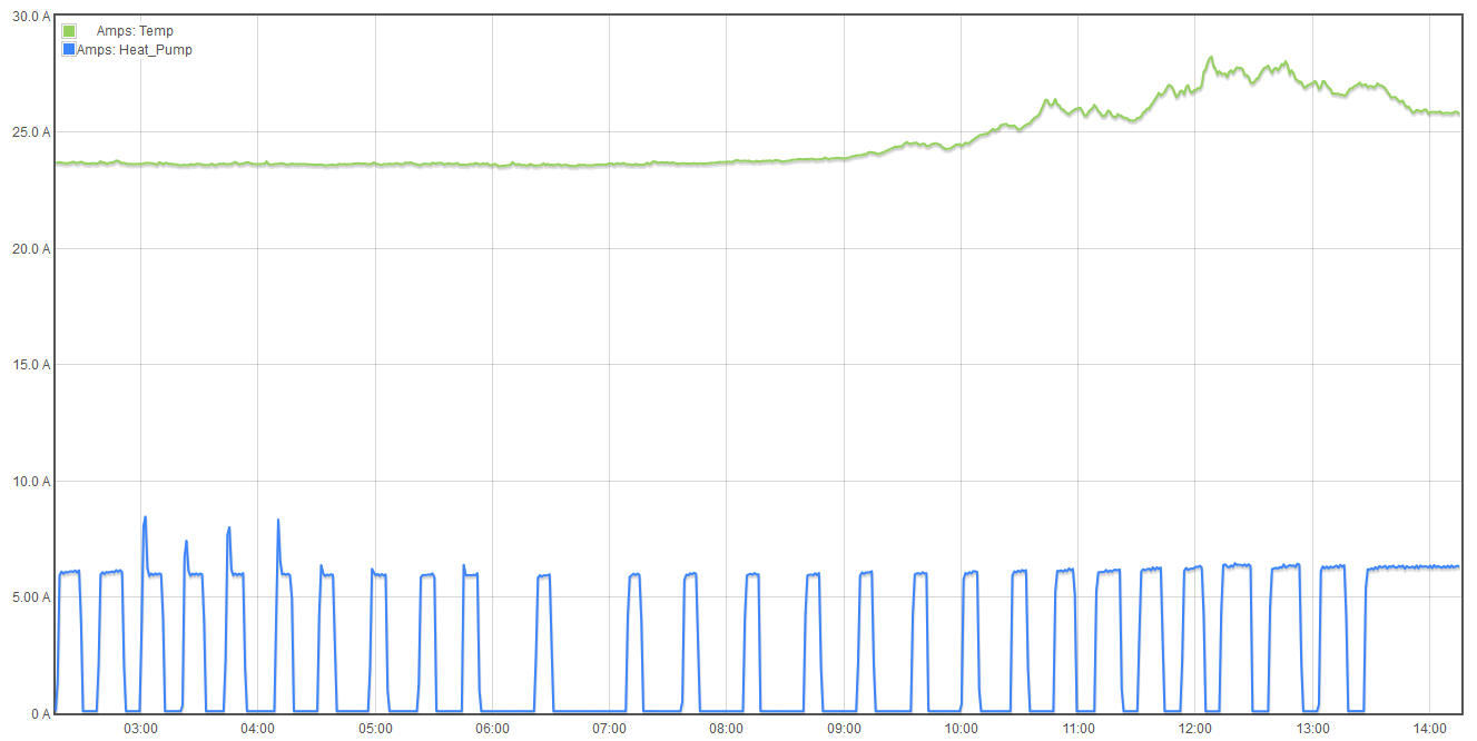
In the attached plot you can see my heat pump amps at the bottom in blue and my temperature in deg C in green both show as amps. For the temperature just read the temp amps directly and 1 amp = 1 deg C. I would have used deg F but then because they both share the same scale it would compress the heat pump amps much more than this does. It’d be better if in the new graph if individual y axes could configured for each parameter being graphed. Like you can do in the original graph.
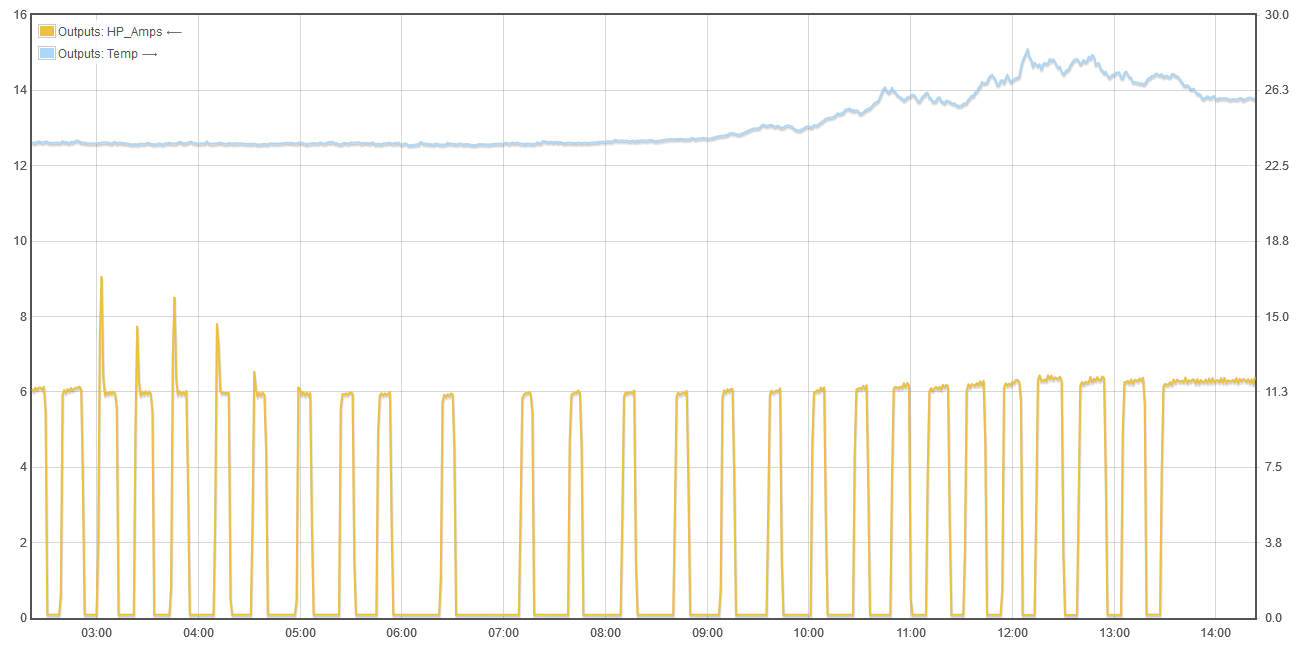
Using original graph I had to turn heat pump amps into an output in order to plot it because Amps is not a choice for plotting in the Feeds menu. It looks like this. I’ve plotted heat pump amps on the left and deg C on the right.:
An advantage to the original graph is that it allows independent y axes to be configured but its disadvantage is having to over come the lack of amps in the Feeds by creating an output.
My interest in this is the spikes in the heat pump amps. These represent times when the condenser fan was not running as it should. Pressure and hence amps would build until the fan either turned on or the system shutdown on high pressure. In these plots the fan turned on but it was late. I’ve had cases where the unit would shutdown on high pressure and sometimes lockout until reset by power cycling it.