I just recently purchased and installed an new IotaWatt and for the most part things are great!
I do have a question around CT Reversed in the status page.
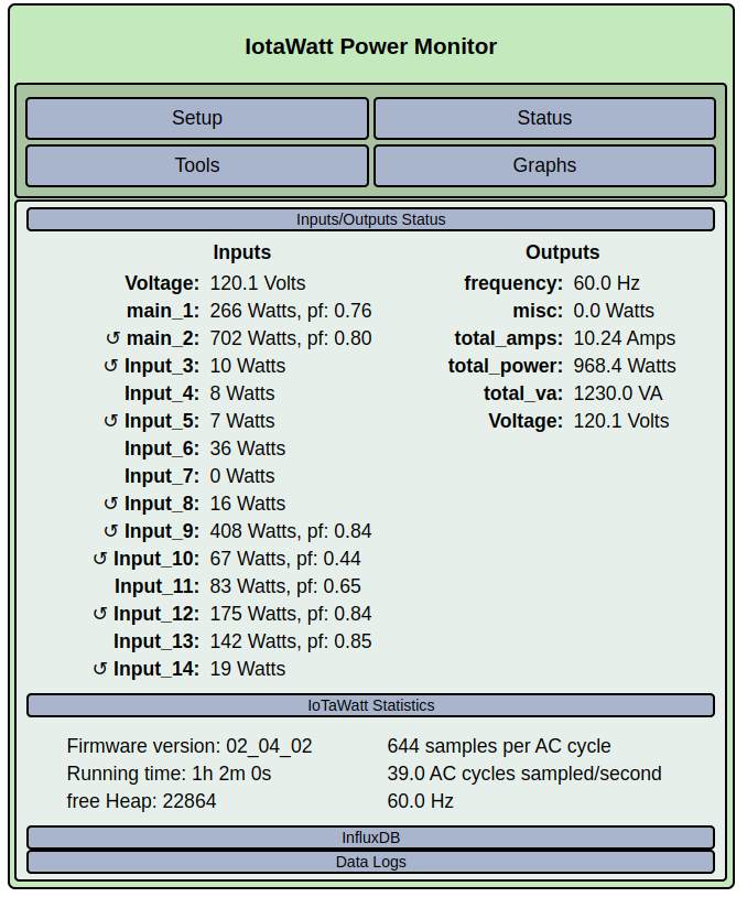
The first question is around the main_1 and main_2 CTs. Both are installed the same direction on the two main lines (left is main_1 and the right is main_2):
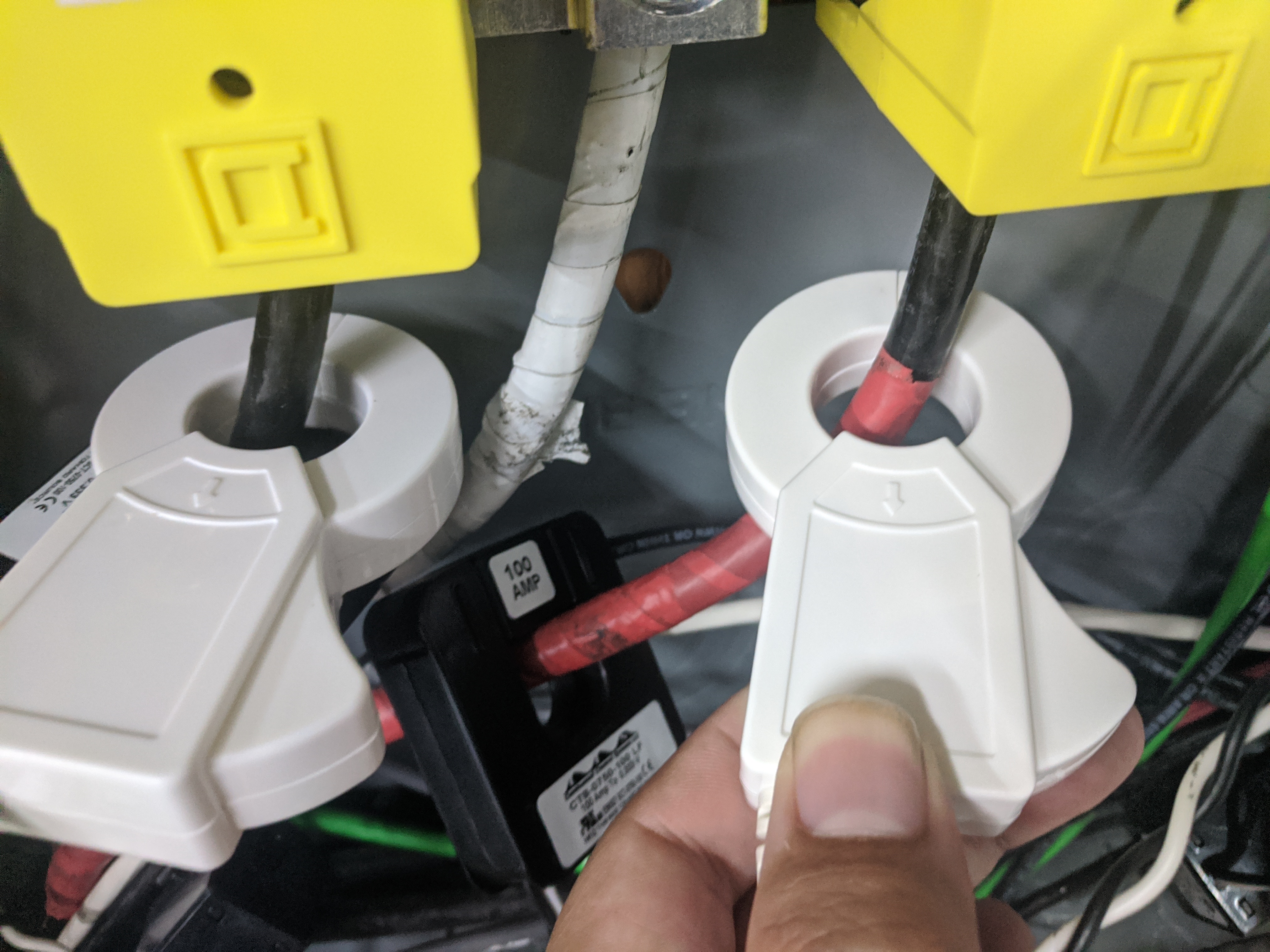
Additionally, Input_3 and Input_4 have the same issue. The top is Input_3 and the bottom is Input_4.
More context (incase it matters) - These particular CTs are actually 120V circuits, despite the wire colors. The home builder got cheap and used an NMB 14/3 wire to run two circuits. Both legs share the same neutral back to the panel.
First, understand that the IoTaWatt is just indicating that it senses reverse current in these CTs, but is automatically correcting those values so that you get correct results. The only time it’s important top get it right is when reverse flow is encountered in normal operation, as with the mains in most North American solar setups.
I really need to add a section in the documentation to explain how to setup split-phase systems, and I plan to do that soon, but in the meantime I just went over this in another post that should explain things somewhat:
Hopefully that will put your mind at ease. Whichever of the two mains is showing reversed can be physically reversed (flip over) or logically reversed (check the “reverse” box in the CT setup). Same goes for the 50A CTs that are reversed. If they are all installed as in the picture, with the arrows pointing away from the breakers, then all of the channels showing as reversed should be in either even or odd rows of the load-center. Because the VT has a non-polarized plug, and I don’t know which “leg” it’s circuit is on, it’s not possible to give absolute advice. It’s all relative, and it really doesn’t matter for accurate results. That said, I have adjusted mine to eliminate the reversed indications.
Update:
As long as the circuit-breakers are 15A, that’s good practice. It saves on copper wire, and the one neutral conductor will never need to carry more current than the greater of the red and black. Although not significant, it can also reduce the voltage drop in the two circuits.
If you have a spare 50A CT, clamp it on that neutral for awhile while using the two circuits, then plot the Amps for all three on the same graph.
Now create an Amps output that is the black minus the red. It should be the same as the neutral.