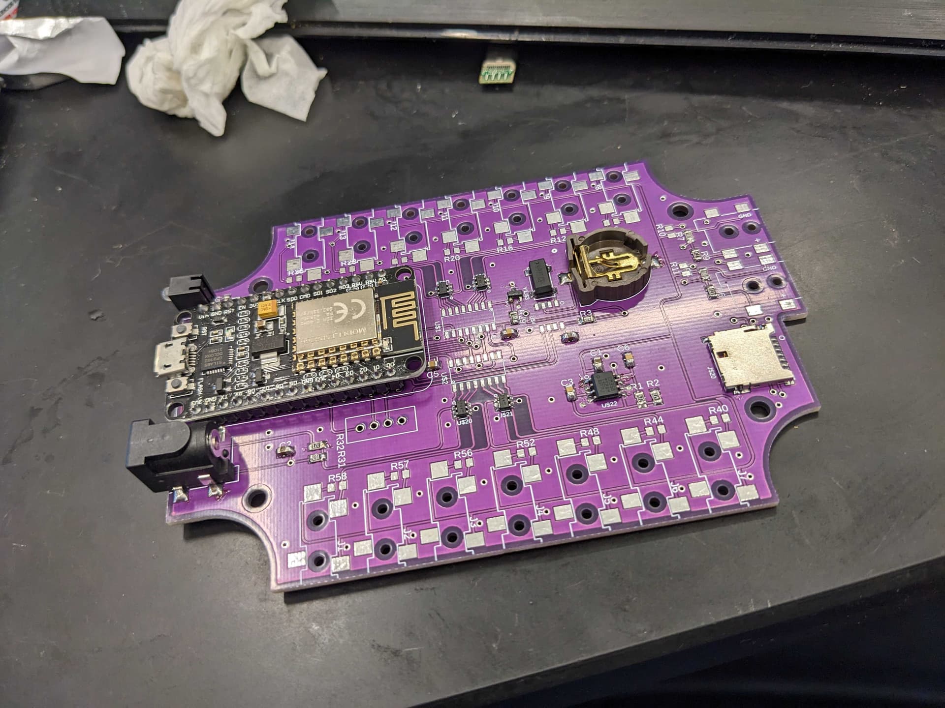
I have ordered the parts from digikey/aliexpress and bought a PCB from JLCPCB. I found the BOM from parts list people posted. Most things are soldered on already.
i am getting some CT from a friend. He has .333Vac output CT.from what i read on from the forums. I do not need the burden resistor and i can solder them directly to the input Pins of the PCB? I would need to connect them to ADC Pin and BIAS? Which is 1 and 2 according to the schematic?
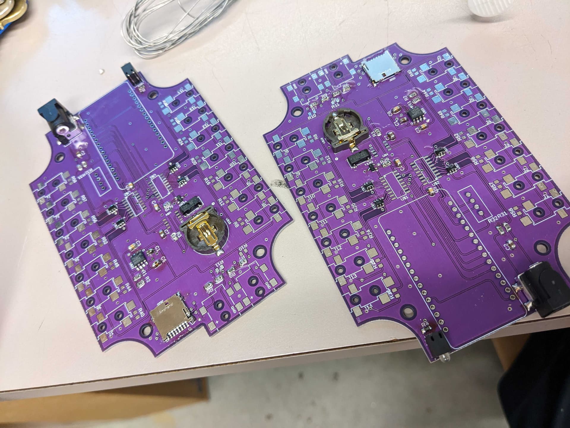
I noticed on the side of the board that has the microsd slot. THere are 2 connectors that has the footprint of a barrel adapter input. What are they used for? I couldn’t seem to find any documentation on that. They are labelled J15 J16. THey seem to be used for ADC 6 and ADC 7 and related to J14 J13.
I have spare PCB if anyone in Canada wants one .
Attatched are photos of my progress so far. I am still missing the RTC chip and the ADC.
I can share my digikey order and gerber file if anyone is interested. I am not sure if i processed them properly. Its my first time creating a PCB this way.
You CAN, but why would you want to?
Iotawatt is designed to use current transformers not voltage output devices. You CAN make it work, but it was designed the way it is for a reason.
Since you are building your own thing you are free to do what you want and take as many shortcuts as you think are reasonable.
I like having connectors, even though I don’t use them frequently. My other device has screw terminals. It was okay. Soldered in ones just seems like a bad idea to me.
You didn’t really state your goals, so if this is for just fun, it probably doesn’t matter. I have some devices deployed that are cobbled together on solderless breadboards. I don’t recommend it, but they have been working fine enough that I haven’t made them better, yet.
This is for home energy monitoring. My friend had those CT laying around so I didn’t have to buy new ones. They are current transformers that just outputs voltage instead of current.
In theory this would be installed in a electrical panel and probably stay there forever or a very long time so unlikely it will need to be taken apart once it’s all done.
I was originally going to order a kit but they ended sales and I didn’t want to wait a till September for restock so I decided to try building my own.
That is like saying I eat to live. There are many things you can eat and still live. Some taste better than others. Some are healthier. Some are cheaper/more expensive. Some leave you wanting more. Some you never want to have a again.
The Iotawatt should not be in the main panel. The CTs probably need to be. Connectors make it easy to change things around and troubleshoot issues. If you never have an issue, you don’t really need connectors.
If your accuracy needs are very basic, you can probably make any CT work. You will have to figure out the numbers to use to “calibrate” your voltage CTs and just leave out the burden resistor. It might be just fine for your needs.
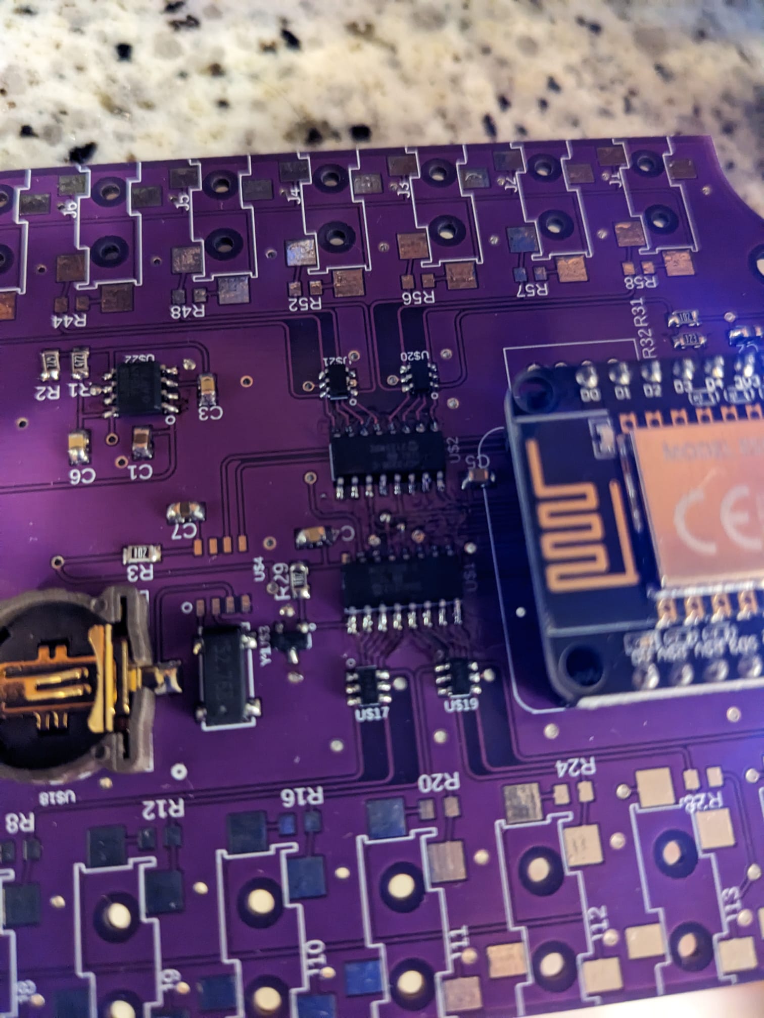
The Iotawatt is not a simple beginner project, so I have great respect for what you have done so far. If it actually works when you first power it on, I will be even more impressed. Soldering the ADCs is likely to be challenging by hand.
I dont really know exactly what i plan to do with it… I am mostly just curious about monitoring power in the house.
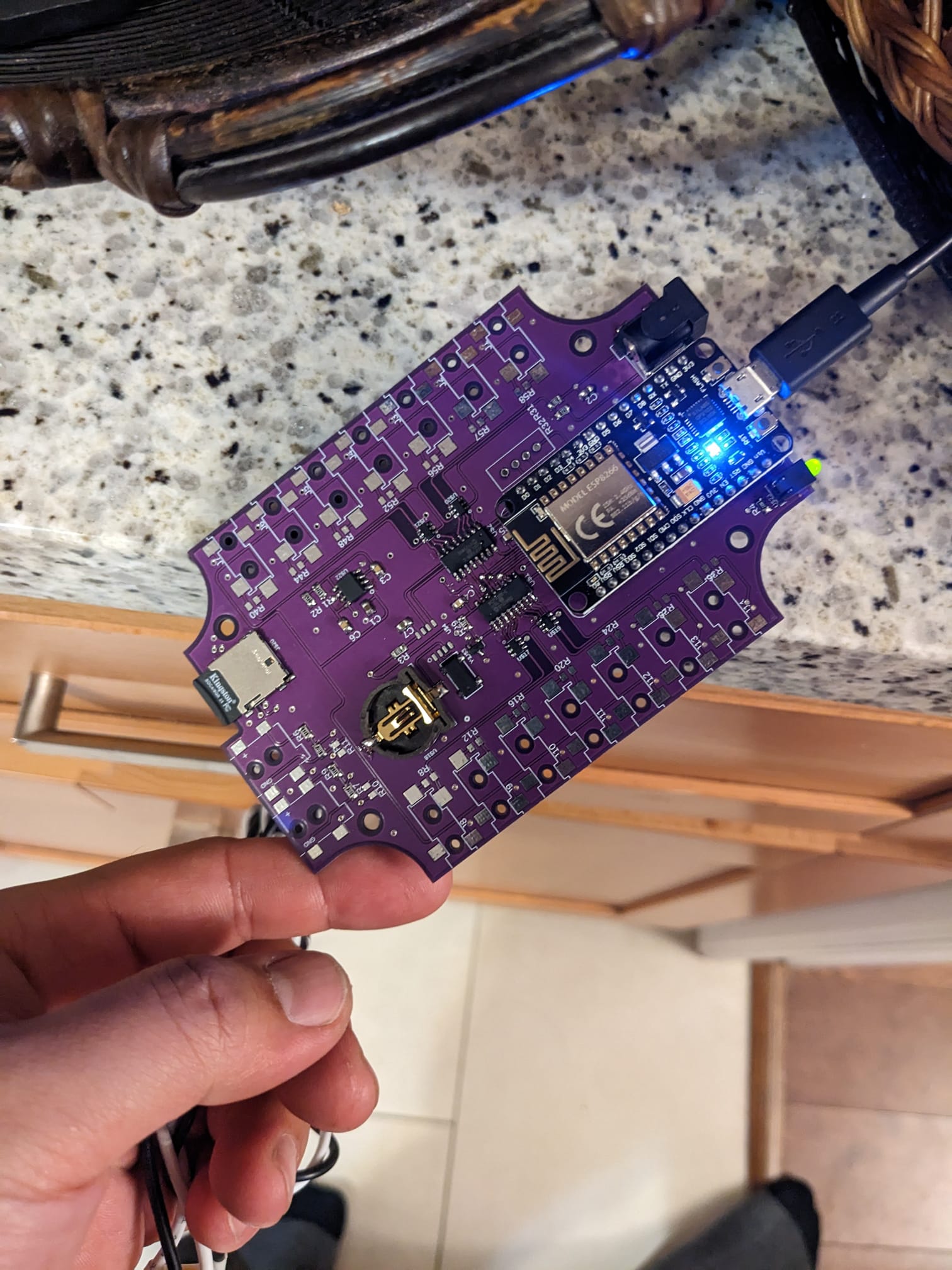
Compiled the software and turned on first time. Figuring out how to use platform io and vscode was more difficult than the soldering side for me. Connected to wifi and was able to talk to it through the web interface.
I have a background in electrical trades and im currently working as technician working on industrial controls. Also electronics is my hobby. Its not my first time soldering surface mount components.
I do plan to put everything into a separate electrical box and design a case or mounting bracket for it.
Looks good and like you have the skills to complete the project. I believe there is a design for the case that can be 3D printed.
I would still recommend the connectors. They probably aren’t that expensive and will likely make your life a little easier later, when you want to change things.
Great soldering job.
I say solder up your grab-bag CTs and see if it works. It’s a one-off anyway, might as well follow the shortest path to completion. You can always desolder and try something else if you don’t like it.
That said, it’s probably worth buying some connectors and having them on hand… If things go well, hopefully you’ll want them.
Nice progress, looking forward to seeing updates.
Edited to add: I have two Iotawatts in my main panel and I would avoid this setup. It took time and some metal to create a safe area for low voltage, and a travel router connected to an ethernet cable to get the signal out. Even now, after it’s all set up and working, I need to pull the door off every time I want to mess with the Iotawatts. It works fine but frogmore is right: Iotawatt outside the panel is the way to go if you can.