What is the role of VT_adapter?
This is an artifact from the past that was used to adapt a VT to a CT input. It’s no longer relevant for two reasons:
The V5 unit incorporates circuitry to enable VTs to be connected directly to inputs 14 and 15 (in addition to input 0).
Virtually all three-phase users use one VT with derived reference.
Thank you for explanation.
If someone has a 1-phase PV inverter and 3-phase grid connectivity would it be wise to use the derived reference?
In that setup the V difference between phases differs by the function of the sunlight available.
Example.
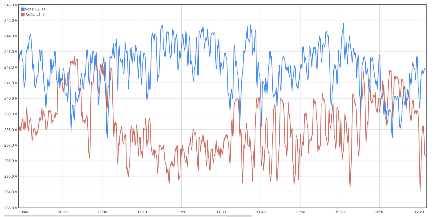
Depends on how accurate you need it to be. Looking at the graph, I estimate that the difference between phases is about 3V or 1.2%. (The statistics at the bottom would have shown the average of each).
Phase A is always correct. Phases B and C can vary. In the big picture, with that 1.2% on two of three phases, the error would be 0.8%.
If you want to check accuracy, take readings from your meter a week apart, then check it against the IoTaWatt.
Here is the statistics.
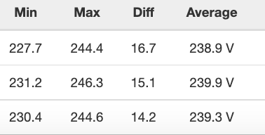
Indeed the averages are similar.
I will give the derived method and the comparisons you’ve suggested a try as soon as I will accomplish my diy meter reader (NORAX3 form APATOR).
Data should be accessible via optical port (IEC 62056-21) although I do not sense any traffic. Might be the case that my power distributor has locked the optical port  .
.
Still have some routes to test … but this is another story.
Don’t know where you are, but in North America a revenue meter must have a display that can be read by the customer.
Poland (Europe).
Yes, there is a possibility that some of the information can be read manually, but I challenged myself on getting the data through the optical port and doing my own remote reading.