Hi
Consider a case in which I have 11 current inputs are not connected and just one input (for example input 12) is connected to a CT.
If the current of this CT (pirmary) is low, there is no problem with the readings and the unused ports show near zero amperes.
But when the current of the chnnel 12, CT is getting larger (about 90A), it affects the unused channels and I see current around 0.2A in these ports. This so called error, exists even if I delete channel 12 from the inputs using the GUI.
This problem is not just related to channel 12 and other channels have the same effect on the unused ports. Even, if there is a CT connected to the other ports, this error affects the readings of that CT.
I think it estems from the hardware.
For more info, I tried to separate the Bias Votage of some ports. In this case, just the channels with same Bias voltage affect each other and the channels which have different Bias Voltage have no effect on each other.
Assuming this is a homebuilt IoTaWatt as previous posts reference that. I’ve moved this post to that category as it’s important to note that this is not a common problem with production units.
I can’t really say with any certainty what the problem might be, but I can give you a list of things to check.
The IoTaWatt doesn’t see the primary current, only a much-reduced secondary current. Without knowing the details of your CT, 90A does not mean anything. Regardless, what is more relevant is the output of the CT which should always be less than 50mA RMS.
Your bias voltage experiment, while suggesting something with the bias, may actually be an indication of a faulty ADC. It would be easiest to segregate the inputs on one side of the board and I suspect you may have done that, which would make the ADC a suspect as well. The inputs to the ADC go through a MUX to a single hardware ADC. A faulty MUX could cause this problem on the other inputs.
There is a remote possibility that a TVS diode is leaking the bias voltage to either rail. To test this, you can just remove them. They are not necessary for normal operation.
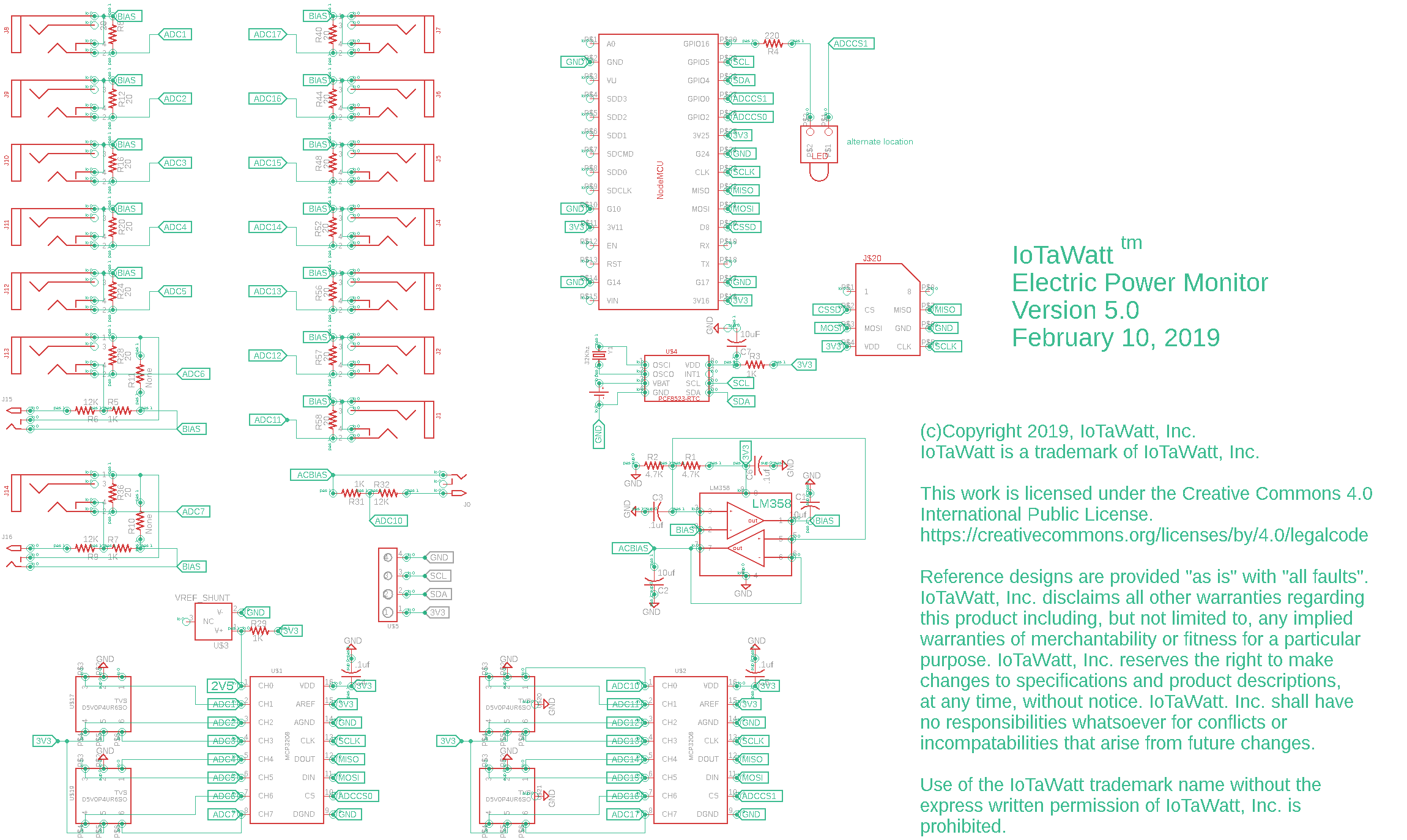
You mentioned that there is a MUX in the board. But, in my version there is no MUX. I just have 2 single ADCs. I attached the schematic you provided in github.
I will remove the TVS diods to see if they are responsible for this problem or not.
There is an OpAmp in my board with 2 voltage outputs.
In this version, when the input current of one CT increases upto 90A, the AC voltage on that input increases above 0.9 volts, consequently. I think this AC voltage leaks to the other AC inputs via the shared DC bias Track. In this case, I can see a 0.3A current in the configuration panel on the unused inputs when there is atleast one high current CT (0.9V AC voltage on the ADC pin).
As I thought that the problem is due to the shared ADC Biases, I started from splitting the ADC Bias for Each Side of inputs. Now, in my board, the inputs 1 to 8 are biased from the first OpAmp and the other inputs (9-15) are biased from the second OpAmp. Now, in my board, the inputs can just affect the adjacent input that have the same DC Bias.
Did you ever see such a problem in the units?
Can you please test it by applying a 90A current to one CT while the others are unused or even used but with lower currents?
Somtimes this error doesn’t appear in the beginning of the power On. Some times it has a stochastic behavior.
make sure your CT secondary wires are twisted and don’t run parallel with any high current wire
keep the traces between burden resistor and ADC short, clean symertic, with good return path (ideally continous analog ground plane with no loops)
keep PCB away from any high current conductors
There are some software considerations:
default IotaWatt firmware is using “overclocked” ADC. According to MCP3208 datasheet the ADC should be driven at 1MHz for 3.3V (probably due to higher imedance of MUX transistors requiring more time for internal capacitor to charge) but is driven at 2MHz. In theory it could cause ghosting but the way channels are sampled with interleaved VT/CT it would affect one channel e.g. when VT is in antiphase of CT.
Used to split the SPI request into two to lengthen the charge cycle but found there was no difference, so eliminated that complexity. They run fine at 2MHz.
Manufacturing testing checks that the bias is at 2047-2048. That is achieved reliably by using 0.1% resistors in the voltage divider that creates the bias level. Also, a shift of one ADC count would not significantly affect RMS Amps.