Hello, I’m hoping someone can help troubleshoot what might be wrong with this:
I have a 100A subpanel off of my main 200A panel. I have two monitors on the subpanel feeds (one on each wire) which are added together as an output to calculate the total results for the subpanel.
I also have monitors on individual circuits of the subpanel to monitor critical items (water heater, heat pump, air handler, well pump). I have then created a “balance” output which is the difference between the subpanel mains, and the individual monitors. (ie. Balance_subpanel = total_subpanel - heater - heat pump - air handler - well pump)
When I plot the subpanel balance compared to the individual circuits, the balance fluctuates with the individual monitors. (ie. balance increase when water heater turn on). In my mind this can’t be right.
Further, the total subpanel power measured by IoTaWatt is ~ 50% higher than the usage recorded by my power company for the whole house! So I think that the sub panel monitors are not working correctly.
If it is of any interest, the subpanel is being monitored at the main panel (next to the iotawatt), and the individual circuits are being monitored at the sub-panel which is about 80ft away (using cat-6 cable). However I’m 95% confident in the result of the individual circuits.
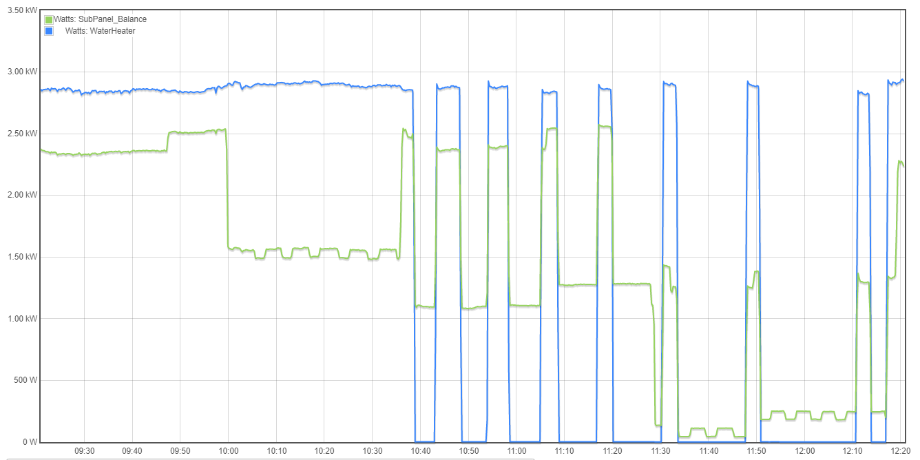
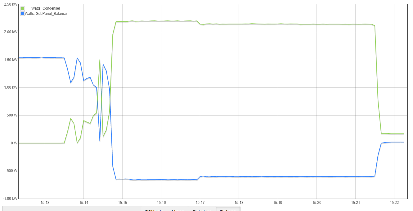
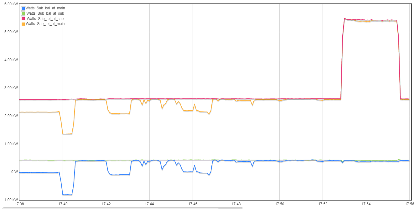
Here is a snip of the graph+ showing the water heater turn on and off, and the balance fluctuating with it.
Thank you for any help you can provide!
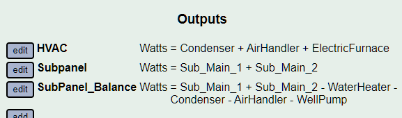
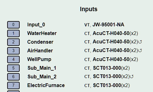
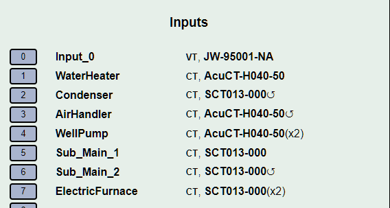
Can you post your inputs setup display?
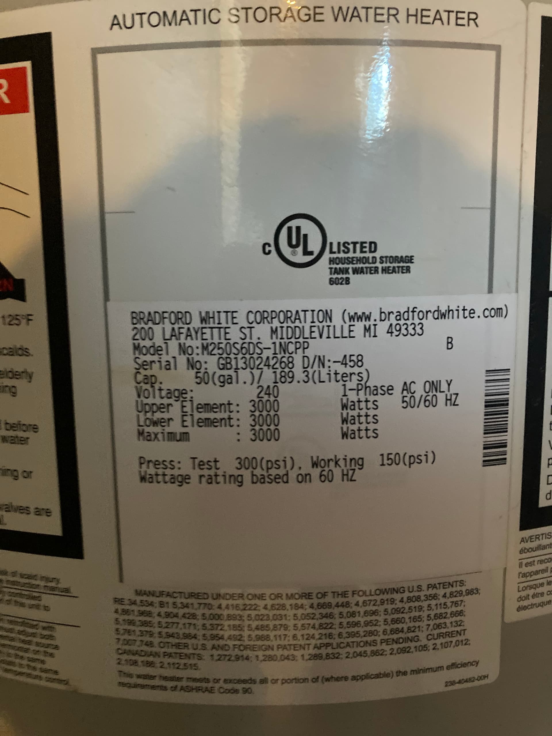
What is the nameplate rating of your Water Heater?
I think the problem is that you have the inputs for the subpanel feeds doubled. Because you are using one CT on each leg, they should not be doubled. Double is used when you only have a CT on one leg of a 240V circuit.
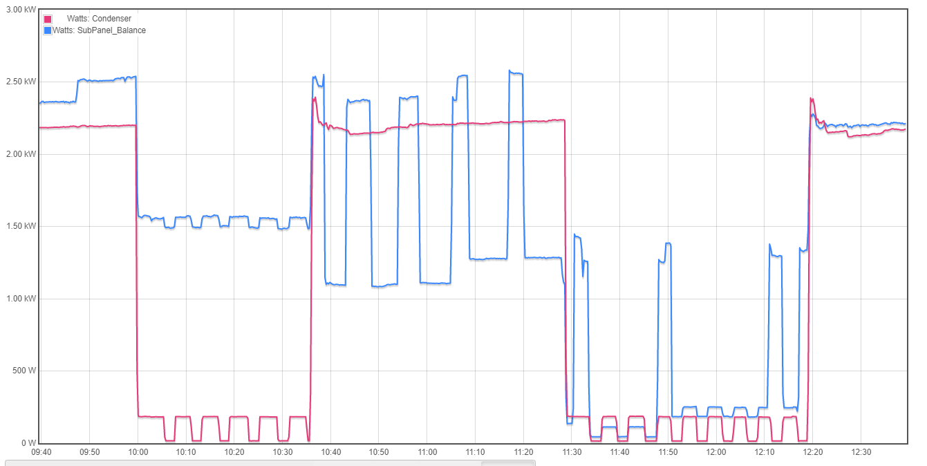
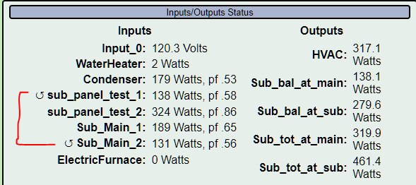
I thought that might be the case, and it does explain the fluctuation with the water heater. However, when I remove the double, then it results in a negative balance. In the picture below (with the double removed), the condenser is running off the sub panel, but pulling more power than the entire subpanel.
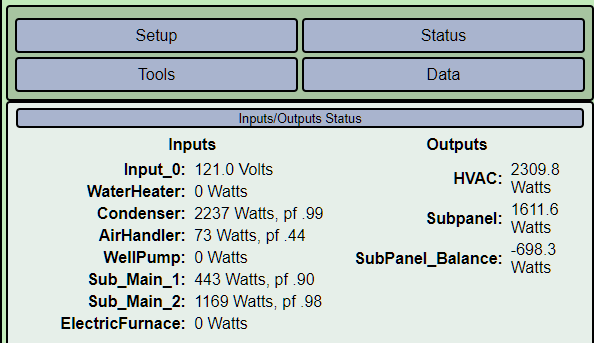
The condenser looks suspiciously like a 120V load. It also has a very high power factor indicative of a resistive load. If that is a 240V load, it would be split with 1119 Watts per leg. I only see that on feed leg 2. Perhaps the “condenser” should not be doubled?
As a check, I just changed all the 240 circuit monitoring to a double leg orientation (each leg through the monitor in opposite directions), and removed the double from inputs. Same result.
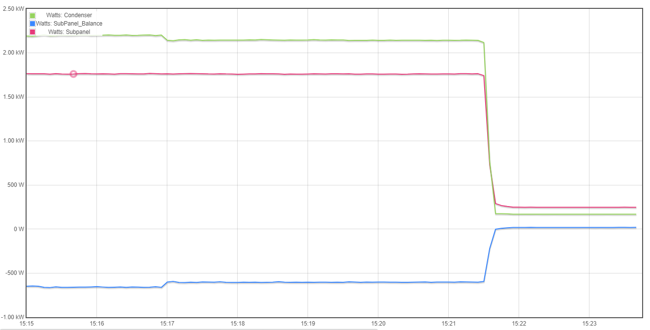
I’ll add monitors to the sub-panel leads at the panel itself, and compare them to the results from the monitors on the main panel. Maybe they are the issue?
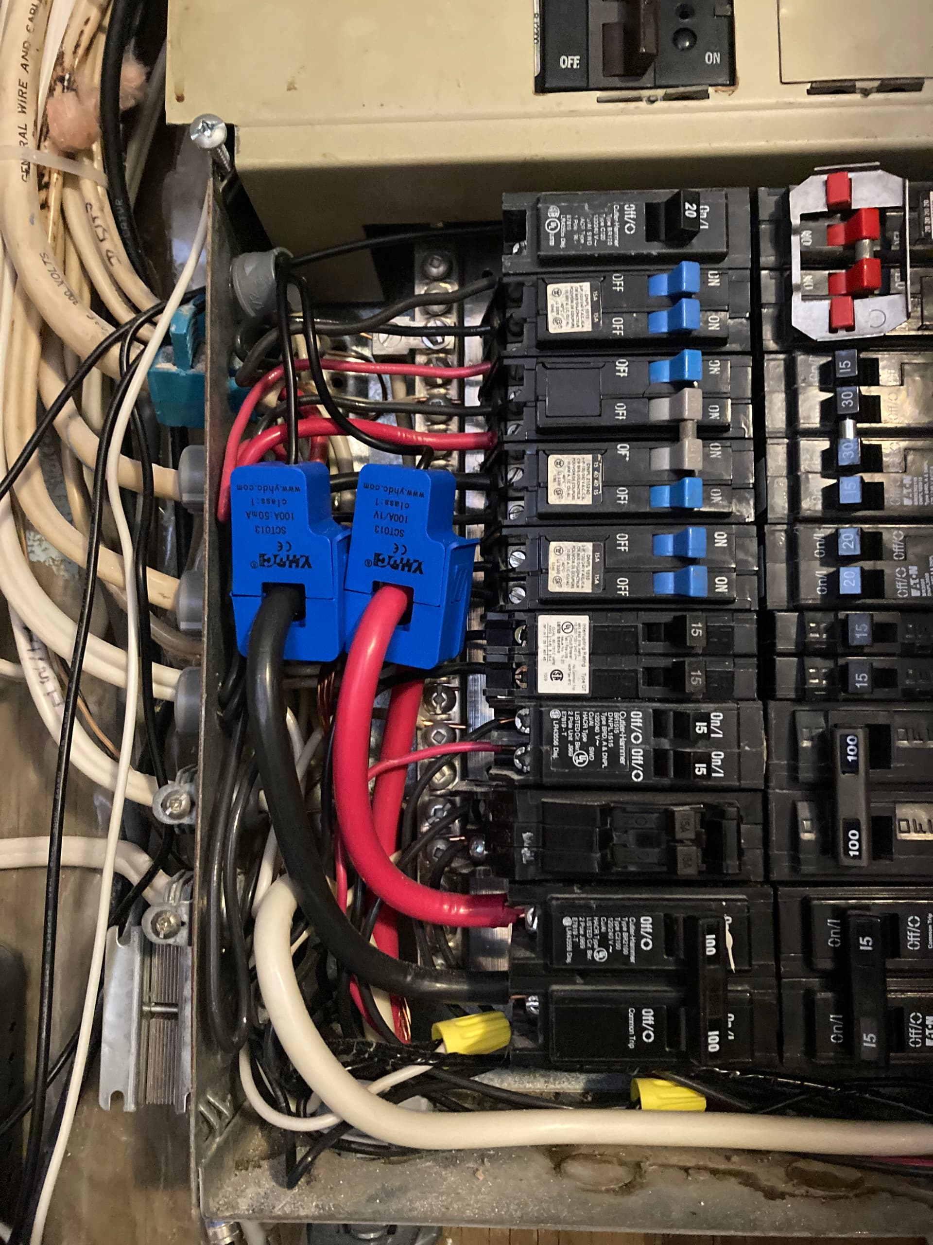
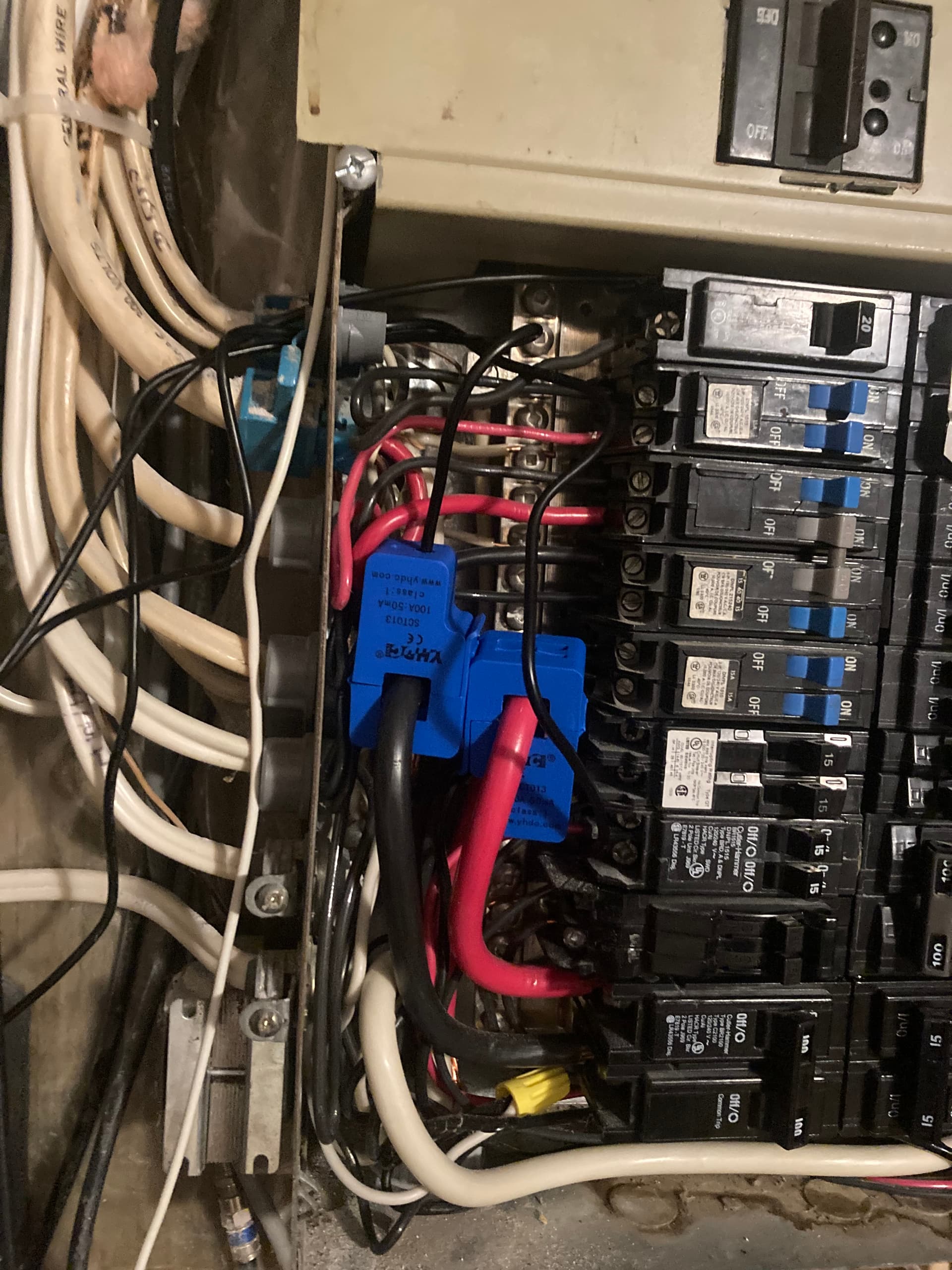
So based on this, I think that my readings of the subpanel taken at the main panel are bad. Unfortunately, that is where I have to take the reading long-term. Any idea what could be wrong? I’ve added a photo of the CT clamp installs. 2x SCT013’s. as you can see it’s very tight. I don’t think I can fit in the extra AcuCT’s I have.
Yup. One of those YHDC 100A CTs is a voltage type (100A:1V). I suspect you may also have more of them in the sub-panel. Also, this one doesn’t look like it but there are some counterfeit SCT013-000 around as well that don’t work properly.
Swapped it, thank you very much. And yes, I have one other in my main panel thoguh so luckily it doesn’t interfere with this problem. But it means that data is messed up…
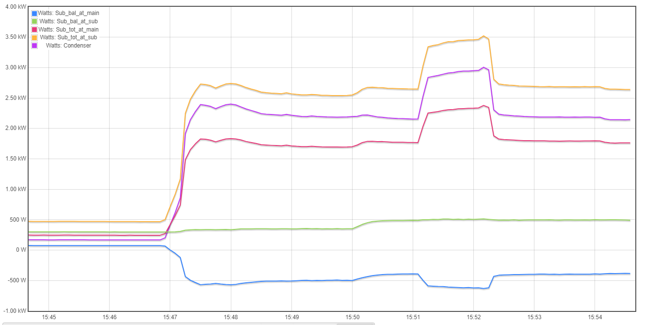
I’m still seeing a difference between the two set-ups. With the main panel monitor going negative. It seems like “sub_panel_tet_1” and “sub_main_2” match closely and is likely the same wire. But “sub_panel_test_2” and sub_main_1" are very different.
Well, the other two do seem to match pretty well, so test_2 and Main_1 are most probably the same wire. One is black and the other is red. I see a pretty large drop in power factor on Main_2 which also has a large drop in power. Check if Main_1 is a 50mA output CT and also check to be sure the mating core surfaces are clean and that the CT is closed fully.
AMAZING! Thank you very much, cleaning the surfaces and putting them back seems to have taken some of the error out. Then I realized that having the two clamps so close together seems to have caused some interference. I flipped the direction of one senor in order to get them further apart and it seemed to have gotten rid of the rest of the error. The graph below shows the deviation as the sensors were moved closer and then further from each other. In the end, it is about 5% error. Given the panel sensor are 80ft away, I’m pretty pleased with that.
Thank you very much @overeasy for all your help. You’re a hero
1 Like
To be more accurate I would say 5% variation. One of them is probably more accurate. Given the sensitivity of the SCT013s in the main panel, I would put my money on the other set, especially if they are AccuCTs. The 80ft of CAT cable should have no appreciable impact as it is a current loop.