ESP32 progress update

Things have been progressing at a steady pace with the ESP32 port. Finally resolved enough of the hardware changes to warrant fabricating a new PCB with all of the functions to date:

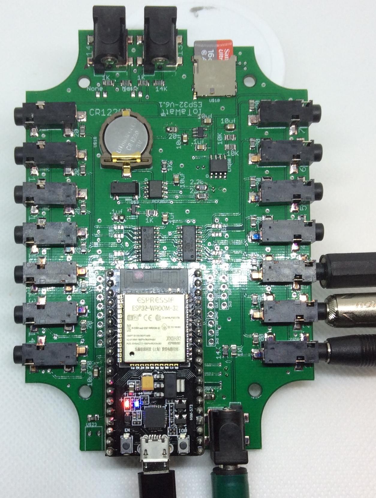
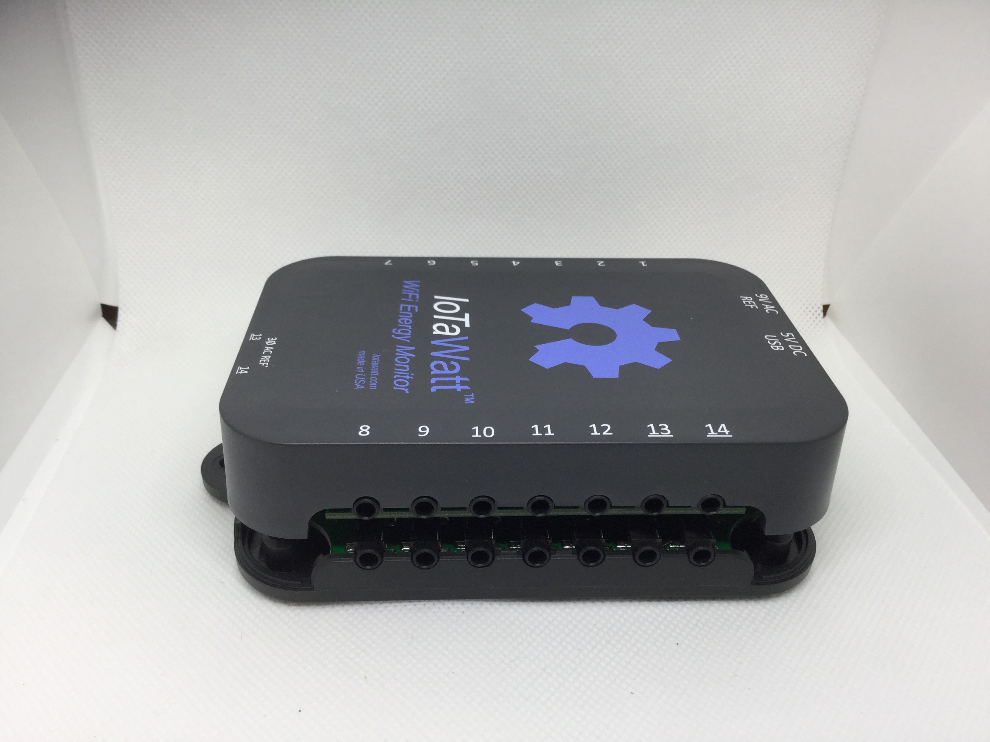
Look familiar? It’s easy to mistake it for the ESP8266 based V5 IoTaWatt. That’s because one of the design goals was to put this into the same enclosure, which this will satisfy. The ESP32 devkit is about the same size as the ESP8266 but has 38 pins instead of 30 as in the ESP8266 devkit.

This version is also laid out the same with respect to the common components so that I could use the same PCB stencil (hand worked the extra components). The final version will probably move some of the components around to better utilize space and accommodate a few more components (more about that later).

The major hardware changes are:

  • SDcard now uses 4 bit data path at 40MHz instead of 1 bit at 20MHz (8x improvement).

  • ADC power, reference voltage and bias are now supplied by an independent 3.3V supply powered directly from the ~5V raw USB feed. The 3.3V available from the ESP32 devkit was just too variable and noisy. With a dedicated power supply just for measurements, things are rock solid.

The major firmware functions are working: Sampling, datalog, web server, inmflux, emoncms, file manager, message log.

The datalog record size has been increased x4 to 1024 bytes. This allows for more accuracy in measurements like VAR, and opens the door for tracking import/export, additional inputs, and other metrics from other sensors.

The plan is to add a second PCB with an additional 14 power inputs. The concept is to make it field expandable with a ribbon cable to this unit and an enclosure riser that would sit between the two, adding maybe 12 or 13 mm to the height. Still researching the connectors, but should have a prototype with provisional wiring soon to test the sampling with 28 channels.

Amazing how fast I’ve run out of IO pins. Have a few input only remaining. Considering adding a 16 port I2C chip to the expansion board and using one or two of the input pins for interrupts from it.

Currently thinking more about adding drivers to support third party bluetooth data like temp, humidity etc.

Have experimented with using an ESP-WROVER instead of ESP-WROOM-32 as it has a lot of additional memory in the external PSRAM. Have an adapter to run with one, and it works fine, except for two things:

  • The PSRAM takes away two more GRIO (16 & 17)

  • The form factor would require a change to a component in the enclosure mold.

So the memory comes at a cost. Right now, there’s still quite a bit of heap using the VROOM, so I’m staying with that. That said, I’m starting to experiment with supporting HTTPS, so heap could disappear quickly. Not sure the PSRAM will solve that, but good to know it’s there.

8 Likes

Awesome! Thanks for keeping all of us posted on the progess… Am so excited!

1 Like

hello Bob,

what about adding IN RUSH function for current measurement, as an extra option, maybe not for all channels ?
very good ideea to add support for temperature measuring or humidity,maybe as extra option for a second board that can extend number of inputs measuring current to extra parameter as mentioned.

1 Like

Any chance of making the ESP32 changes to the code available? I build the ESP8266 code already and run it. Running on a ESP32 would be great.

1 Like

It’s more than a few changes. The whole approach and operating environment is different (and the hardware is changed somewhat as well). I do expect to publish the firmware and schematic when it’s done, but right now it’s still changing too fast to publish.

OK. Thanks for the reply. Will keep tracking the progress of ESP32.

1 Like

Fabulous to hear. I personally have swapped to ESP32 for new Arduinos, the Dual I2C and more features really make it a no brainer compared to ESP8266, when the price is really not that much more.
The ESP32-CAM-AI-Thinker are about the same price as ESP8266/nodemcu’s which is insane.

Looking forward to more updates and design decisions!

It’s pretty exciting to see the new model coming along so much!
From reading your earlier entries about getting the certifications for the current model, I imagine that may be a challenge once you have the hardware and firmware at a point you’re happy with it.
Is there somewhere people can express their intent to purchase a new ESP32 model should it become available, so that you can really gauge the level of interest and be able to make a well informed decision on whether it is worth going through the effort.
You maybe even could use that info to help gather contributions (like pre-orders) so the cost of getting it certified isn’t such a big upfront hit, if there is enough interest.

I’m planning to buy one of the existing ones soon, since my apartment is small and only has a few circuits to monitor, but I’d love the ESP32 to set up for my dad’s place, since he has WAY more individual circuits, as well as Solar and an EV to keep track off, the added I/O and frequency of measuring would be a boon.

Love the work you’re doing on this, both the new model and the whole existing open source project, it is a really stellar example of the power of open source and people power. You’re a utter champion Bob!

I’m a little late to the party, but I just wanted to share some thoughts on the expansion board mentioned in the first post.

Rather than using a ribbon cable to connect a second unit, you could instead install some form of mezzanine connector on the underside of the board which would allow you to use the existing case as-is.

If the expansion board sat underneath the main board and was supplied with a case extension (Basically just a short tube of plastic that accepts both the original lid and base), upgrades could be performed by the user. (Open the case, connect the new board up, put the case extension in and stack it all together with longer screws.) This would mean that less surface area is used, no new mounting holes are required and all of the parts from the original unit (Except the shorter screws) are used reducing waste.

You mean like this?

This is a working 29 input IoTaWatt. The pros and cons:

Pancake Design:
Pro:

  • Field upgrade
  • Simple assembly

Con:

  • More expensive connectors
  • Adds manufacturing cost (components on bottom)
  • Very costly to produce mold for spacer sleeve (estimate ~$10,000)

FFC Cable Design:
Pro:

  • Field Upgrade
  • Can have extension maybe several feet away
  • Can still pancake two boards with short FFC cable and 3Dprint spacer
  • Uses existing enclosure mold for extension
  • Inexpensive SMT FFC connector only component added to main board.

Con:

  • Need to route a slot for cable in enclosure base. I have quite a supply of unused bases, so could ship 2 with extension kit initially. Can have existing mold modified to add slot in new units.
  • Slightly more complicated to connect FFC cable.
  • Cable should be shielded and protected if running for any length.

So the FFC would add less than 30 cents to the cost of a board, so all units would have it and be field upgradable. You can get FFC with any number of conductors. I’m looking at a 1mm pitch with 16 conductors, which will allow the expansion board to have the potential for a variety of other uses including I/O expander with interrupt capability.

That’s my current thinking. The prototype needs to be laid out again to accomodate the FFC and an ADC selection logic to reduce the ADC GPIO requirement from 4 to 3 so I can use an ESP32-WROVER with additional SPRAM, which has the potential to be a game changer for RAM inhibited functionality.

Thanks for the interest, and as always, discussion is welcome.

Yes that’s exactly what I meant.

Fair points on the costing, I would however question whether or not adding the slot to the existing mold would be inexpensive as the mold is a negative - I’d expect at least one part of the mold to need to be remade. Additionally the entry point for both units might need to be different (As you ideally don’t want to be needing to bend / fold a FFC cable) which would double the cost and increase the part count.

I’d also be concerned about how robust FFC cables are - They are fine when contained within an enclosure, but they are a little too delicate to be exposed. Shielding shouldn’t be an issue over a reasonable distance if you ran a ground between each analog signal and used differential signaling for and digital signals.

For very long runs I’d consider allowing remote units connected to the same wifi network instead with one acting as the “master”. It really becomes a case of synchronising config and importing / exporting / buffering data which if implemented could possibly solve the expansion issue in all scenarios.

Personally I’m liking the pancake style enclosure with an internal FFC cable. I guess it all comes down to the cost of the new mold vs the modifications to the existing mold - Which in turn comes down to how many expansion units you think you’ll sell. 3D printing the expansion spacer sleeve could be an option for lower volumes.

Bob - this looks and sounds fantastic. I currently have one IOTAWATT.

I need a 2nd unit to monitor my solar and grid consumption as well as provide additional Clamps for my house main switchboard.

I am in a bit of a quandry as to which way to go and would like (if possible) for you to summarise your thinking on upgrading existing IOTAwatts with the 32-bit module - is that your thought process - or is it only going to be a new offering ?

As it is now - my main switchboard has 20 circuits - and a 3phase feed incoming

My meter box is about 10 metres away and this is where the grid comes into, as well as the two 3 phase solar inverters (probably end up with a 3rd one soon - or a 3 phase battery system - not sure yet on that)

So i have a couple of options

  1. Purchase another IOTAwatt V5 and deploy it to my Meter box with a couple of unused channels
  2. Purchase a 3rd unit to go into my switchboard to enable me to instrument all of my individual circuits.

I have plenty on my plate at the moment so am not in a tearing hurry, but wanted to get some context around the upgrade path (if there is planned to be one) and/or the need for any Australian testers/Beta users of the new system ?

regards

Craig

Hello @craigcurtin,

This ESP32 project is nowhere read for primetime. My thinking is that I may be able to make some serious progress over the winter and hopefully have a prototype unit ready to go to early testers late Spring. That’s optimistic.

While they look similar, the upgrade path from the V5 is to replace. If I do adopt the ESP32-WROVER, there will be a subtle change to the enclosure as well. My thinking, if I ever get to manufacturing, would be to offer an upgrade deal to previous V5 purchasers.

I really haven’t been coding all summer. I always told my kids that the definition getting older is that you don’t get summers off anymore, so I’m trying to regress. Coding is easy in the winter and passes the time.

1 Like

OK no worries, good to understand the process and very much appreciate your honesty of where you are upto.

Will put together an order for a 2nd unit in the next couple of days and make it happen !

This will let me monitor my Solar and Grid (and potentially battery) and get a whole of system view of what is happening.

Keep up the great work

Craig