Less than a week with an IoTaWatt, and trying to figure things out…
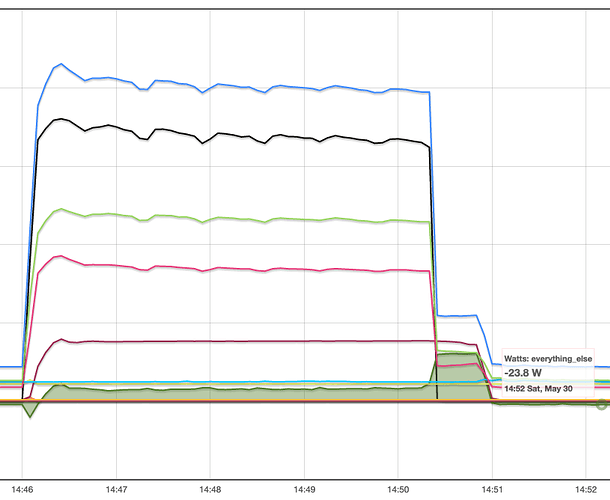
I’m driving myself crazy with a calculation for an output called everything_else which is the two main phases minus all the monitored circuits.
Steady state, everything_else seemed to be about 50 W. OK, not too bad for parasitic draws from various stuff in low-power mode around the whole house.
To sanity check that, I just turned off all circuits in the house that aren’t monitored by CTs, and now I get… ~ -25 W. Huh whut?
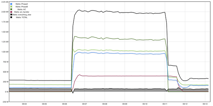
OK, let me turn on a big draw and see what happens, so I kick on the air conditioner, and now everything_else jumps to ~ +82 W. And, after the compressor shuts off, but before the air handler does, everything_else jumps to ~300 W for ~30 seconds.
Before I go totally crazy, am I running into an accuracy limit of the CTs, or some electrical phenomena (power factor?) or have I installed or configured something incorrectly, so far?
Argh…forgot to screen capture the legend; if it helps:
blue = total
black = AC compressor
green = phase A
red = phase B
red/brown = AC air handler
green fill = everything_else
vertical divisions are 500 W (total hovers around 2 kW)
Looking at the graph, I suspect the later. -30 to +80 is not CT inaccuracy. That’s about 5%. I’d expect maybe 1% in this scenario.
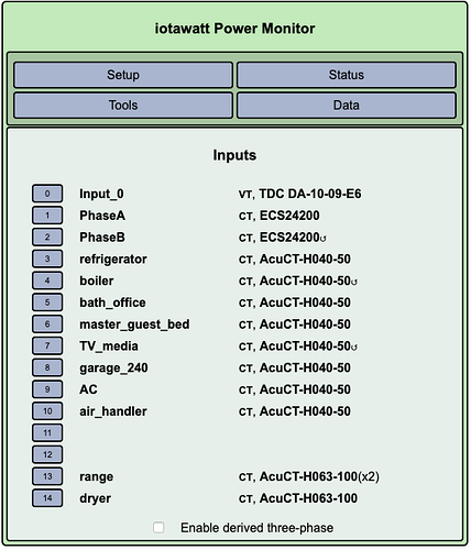
I’d like to see your inputs configuration display. Typically AC compressors are two-wire 240V. It’s possible your air-handler is three-wire, and I’m looking at the ~300W difference between your two mains. Id like to see a picture of the panel with the cover off showing the CTs and breakers, as high res as possible.
Lastly, a screenshot of the status display during this experiment with the AC on and all the other breakers off might be informative.
Oh, thank goodness it’s likely I made a mistake. 
I played around with the inputs, toggling some of the reverse checkboxes for the ones marked with the 3/4-circle arrow, to no avail. But, given my ignorance with how this works (so far), I probably haven’t yet hit the right combination to make it correct. Here’s how it stands right now.
I played around with the toggles for reverse on a couple of the inputs, but in my ignorance this was more haphazard than anything else. (I do want to correct all of them before I button up this project.)
Currently set to “reverse”: PhaseB, boiler, TV_media.
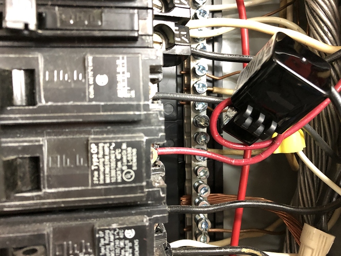
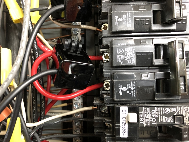
A full photo of the panel may not have the resolution you desire, so for now, here is a closeup of the circuits in question.
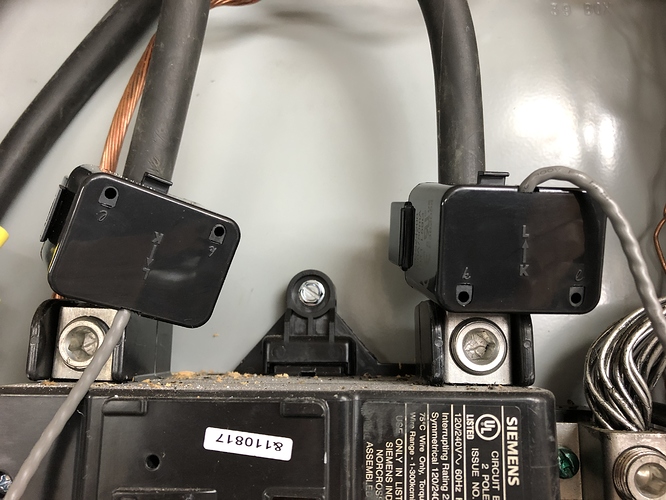
Mains (one clearly backwards):
AC: one leg forward (black), one opposite (red):
air_handler: one leg forward (red), one opposite (also red):
Clarification: my prior experiment was with all circuits off except those with CTs. I can’t quite do an all circuits off (except the AC compressor and air handler) because I need the IoTaWatt circuit on, plus the “office” circuit on (for the wireless thermostat to control the AC), which has the router/switch/wireless-access-point. If that’s OK, I will repeat the experiment.
I can correct the orientation of the three CTs first, if that helps, too.
Thank you, @overeasy!
I do think that the reverse on “Phase B” is wrong. Looking at the photo, one main is already reversed physically, so either neither should have reverse checked or both should, but If you do not have allow negative values checked, it doesn’t really matter.
I would like to see a picture of the whole panel, along with something that labels the breakers.
Have you read the split-phase documentation?
(No changes yet today…hopefully later.)
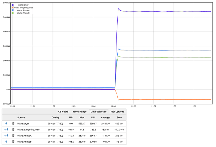
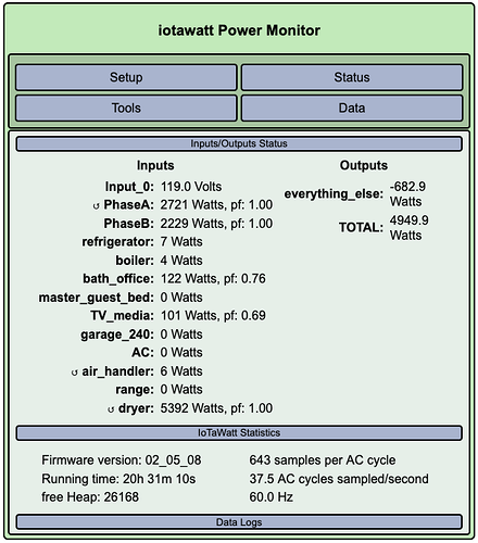
But, more unexpectedness… Running the clothes dryer, that circuit reports a live, steady-state reading of 5.40 kW, but yet the two main phases report 2.72 kW and 2.23 kW, which added give 4.95 kW. ??
Here is the Graph+ for the dryer and main phases (plus the Everything_else), and the Status window.
Huh, then I just noticed PhaseA, air_handler, and dryer have the reverse symbol in the Status window, yet the Input window still shows Phase B, boiler, and TV_media as having the reverse symbol.
Yes, I have read the doc, a few times. Probably going to have to read it a few more!
My VT (and IoTaWatt) are plugged into a circuit on Phase A, if that makes any difference, or if there is a convention that I should be following instead.
Discrepancy resolved. PhaseB CT clamp had come loose; I resnapped it back tight and now the world makes sense again. (When it doesn’t, it is always good to go back and verify your assumptions.)
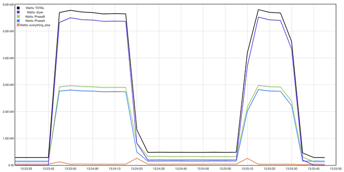
Total is higher than the one clothes dryer circuit, and the Everything_else output calculation doesn’t appear to be going negative anymore:
I’m pretty sure it was tight when I first installed it; my graphs back to the first few days after install show no negative values for Everything_else, even when testing large draws (the oven/range). Sometime Saturday morning-ish, Everything_else started to go negative with large draws.
And, as part of cleaning up my ham-fisted first pass, I cleared all the reverse input settings, and then noticed both main phases were reversed. So, following the doc, I reversed the polarity of the plug for the 9V reference transformer and–voilà!–all is good with the main phases again.
Bad user. No donut!
I don’t know if this will resolve your issues with the AC and air-handler, but it’s promising.
Subtle thing I want to point out is the little bump in everything_else at the start and end of the dryer run, and for that matter, the way both the mains and dryer do not run up to full load in a straight line. It’s what you get when you look really close.
The entire plot covers a time-span of 145 seconds. The data, from the datalog, are five second averages. Looking at your status display, you can see that there are 13 inputs, and that the IoTaWatt samples roughly 39 times per second. So each input is sampled roughly 3 times per second. Each sample will represent about 7% of the average for a five second interval.
So when we see the mains ramping up to 5kW, it happens during one of those sample intervals, and 7% of 5kW is 350W. Moreover, when the dryer starts, it will have a short inrush current as the motor starts. Since the sampling of the mains and the dryer are not simultaneous, the timing difference can cause the weighted averages to be different by up to that 7%. This reasoning is supported by the return to the same steady state value after the state change interval.
It’s important to note that in terms of kWh, this is insignificant. Also, on any plot of a significant time period, or a lesser load, it would not be observable.
Also, it’s hardly noticeable at all at the end of the second cycle or smaller at the start of the first cycle. All that has to do with the timing of the ramp-up, in fact it seems to go down slightly at the end of the second cycle.
What’s most significant is that it returns to the same approximate value after the transitions. Looking at the csv data would tell the whole story with exact five second precision.
@overeasy, you are right…I didn’t repeat the same experiment. I just did that, and it looks like the AC/air_handler behavior is now the same as the dryer: I’m getting consistent values for the main phases and no (major) negative or weird values for Everything_else, except during the transitions.
Interesting to hear a little bit about how the IoTaWatt does its sampling, and it makes total sense, and I’m okay with these small, short-lived anomalies.
Well, until an IoTaWatt Pro comes out, with all channels simultaneously sampled. 
1 Like
