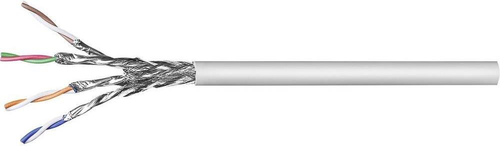
Extend length of cables for voltage and current sensors

Hi:
We’re planning on using the IoTaWatt in an industrial 3-phase setting where the breaker boxes are huge, so we would like to extend the cables of the sensors (for both the current sensors and the voltage sensors) for routing out of the boxes up to the IoTaWatt.
We are electrical engineers but would still like to hear your recommendations about how long can we go with the cables. I guess the voltage sensors are less sensitive to cable length since their current is minimal, but I’m concerned about the current sensors. We’ll be using 100 A and 200 A sensors because their internal diameter is larger, not because we need their full scale (we’ll be monitoring facilities where several cables are used for each phase, so the current is split, thus reduced, among several cables).

Thanks a lot!

1 Like

I’m interested to see the answer.
I can share my experience, I extended them using Cat 6a S/FTP cable, I used all the 4 pairs (1 per CT).
I compared the measured values between one extended CT with one non extended and I did not really see a difference.

Thank you daniweb.
What cable length did you use?.

1.5 m
It looks like this:

Did you already look at this page?
https://learn.openenergymonitor.org/electricity-monitoring/ct-sensors/extending-ct-cable

I’m not an electrical engineer, so take my 2 cents for what it’s worth.

This question keeps coming around, and @daniweb has pointed you to the EE formal opinion. I don’t think you can go wrong with that, but I do have some comments on your approach to this problem.

My impression concerning the impact on VT vs CT is opposite to yours. With the VT, the transformer is a voltage source, and as such will produce a current that is a function of the resistance of the circuit. IoTaWatt measures the voltage drop across a 1K resistor in that circuit as a proxy for line voltage. The voltage across that 1K resistor is a function of the current in the circuit. So the voltage sensed by IoTaWatt is directly affected by the resistance of the circuit, and the extention cable adds resistance. All that said, any added resistance can easily be calibrated out.

CTs are a different animal. The are a current source. Regardless of the resistance of the secondary circuit (within practical limits), the current is always the same proportion to the primary current. Doesn’t matter if I use 10 or 24 ohm burden, the CT generates the same current. So if you were to add .5 ohm to the circuit with extension cables, it should make no difference in the current loop or the voltage generated across the burden in the IoTaWatt. That said, you should be conscious of the possibility of introducing noise to these lines, especially where you are inside industrial machinery. Shielding or running inside metal conduit would probably be a good idea.

Beyond that, I do have an idea that you may want to explore. You say the current is carried in several parallel cables, and that you intend to put a CT on each and presumably add the power measured in each to get the total power. That should work fine, but maybe there’s a simpler approach: Lets say that you have three cables in parallel, each carrying a nearly equal amount of current. If you put a CT on each cable and wire the outputs in parallel, I think tyat’s the same as one big CT around all of the cables. In other words, you would only need one extension cable and one input on the IoTaWatt. I will try this on a smaller scale over the next few days.

The other thing I was going to ask is whether you intend to use the derived or direct method of three phase measurement. Regardless, this is an interesting project, and it would be nice if you coud document your experiences in the show-and-tell category of this forum.

I’ll be following along.

UPDATE: I tried connecting multiple CTs in parallel and it seems to work. Here I have three CTs in inputs 1, 2 and 3. They are identical CTs but each has a different primary current. The output sum123 is the total of the three.
input_4 is three more CTs connected in parallel, each clamped next to one of the inputs 1, 2, and 3. You can see that the power is the same as the sum of the individual CTs. (<.2%).

image

The inputs are all ECS1050 CTs (50A:50ma). The advantage here is that you can measure the sum of multiple circuits (or individual parallel cables in one circuit) using one Input on the IoTaWatt. The downside is that the total power cannot be more than the capacity of one CT, and all of the CTs need to be the same. So with the individual CTs on inputs 1, 2 and 3, the total current for the circuit could be as high as 150A, while the three combined cannot exceed 50A.

Depends what you want to do. Extending this to a more general case, I think that you could combine two or more identical CTs in a household panel using a simple stereo headphone splitter.

The lead extension on the VT will have a minor impact on accuracy as the resistance of the cable is very small in comparison to the 1K resistor.

Lets say the cable resistance is 1 ohm (probably will be much less). Voltage across the 1k resistor will be V x 1000/1001 that is only a 0.1% error.

Hello all,

Thanks for replying. I’m also in the team with AG19.

Sorry about the late reply. We’ve been doing other tests unrelated to extending the cable.
We’re now planning to use Belden 5500FE, which is 22 AWG, two-conductors, twisted and foiled for audio and security rated at 16 ohm/1000 ft. We’ll let you know about it.

We would like to clarify some things.

The industrial setting is not very “industrial”. We said industrial only to differentiate from a residential setting. Apart from all the breaker boxes the place only has a diesel power plant used for power backup.

Regarding the parallel conductors. We intended to use only 1 per phase and multiply per the number of conductors per phase (n). So far we’ve found the currents are not very close to 1/n. That’s what we’ve been testing these days and now we’ll try to characterize whether the currents are always distributed the same with varying load conditions. That would allow us to use only 1 CT per phase and a formula for the total, lets say PhaseA = 2.8*CT1. If that’s not possible then we’ll use one CT per conductor. Here’s where wiring several CTs in parallel would come handy, since some circuits are 8 conductors per phase !!! Thanks for doing the test, overwasy; it looks great. BTW, we’re using the derived method for voltage sensing.

Here’s our temporary installation for the multiconductor test. The breaker is way overspecified since the currents are only about 50 amps total per phase. The breaker is actually placed horizontally. We’re using 200 A SCT019-000 CTs mainly because conductors are AWG 3/0 or 4/0.

The IotaWatt status looks like this. Inputs 1,2,3 are for phaseA in the breaker, 4,5,6 for phase B, and 7,8,9 for phase C. Voltage sensing is at phase C. Notice that we’re having some trouble with the 3rd conductor in phase B ( CT 6). We still have not figured out what’s the cause for that.

Thanks again for your suggestions.

Couple of things that got my attention:

I think the current in each of the three parallel conductors will vary with resistance. Not knowing the gauge or length of each, I can’t quantify it, but there could be significant (where the cable resistance could be milli-ohms) resistance in the connections. But I don’t think that’s what’s going on. Resistance would not change the power factor, which varies a lot between some of the cables. Especially that third conductor with a PF of .78. That cant be right.

I know it would be tedious, but labeling each of the CTs and cables and moving the CTs to each of the six combinations on each phase, and taking a screenshot at each combination, some patterns may immerge. You may determine that there is both a variation between the individual cables due to resistance, and a variation between CTs that may be related to proximity to adjacent cables, incomplete closure, or as in the case of that third CT, a possible defective CT.

What is the length of the cables, and what is the total amperage of one leg of the circuit?

Take a look at these CTs from Echun. They could go around all three cables (or more) and plug straight into the IoTaWatt as a generic CT.

ECS90-S
ECS120-S

Thanks.

The 9 conductors are AWG 4/0, 15 m in length. Currents are in the range of 10-15 A per conductor. There’s definitely something strange with that specific conductor, specially with the PF. Even before your latest reply we already tried switching the CTs at the IoTaWatt inputs, we also switched the CTs at the conductors and also experimented with the angles (+120, +240). No apparent cause for the problem and our CTs are labeled, so we checked the configuration before each test. At a point we were wondering if something could be wrong with the way PF is being computed. Maybe something related to zero crossing, or the fact we’re using the derived method for voltage sensing? We also measured harmonics ratio (between phases) and saw no significant difference. All three measurements are below 0.30%.

Anyway. We moved on for now and will get back to that circuit and issue once we make progress. Now we changed the CTs to another circuit with 2 conductors per phase. So far so good. We’ll use the CSV Output option at the Graph menu to analyze data and check whether we can use only 1 CT per phase

We will consider the larger CTs you’re recommending but depending on the accuracy we get from the single CT per phase configuration it may be unnecessary.

We’ll keep you updated.

I have to wonder if there is a bad connection and there may be some arcing going on. If you have an infrared camera, might take a look at the connections and components in that leg. Seems to me that a power engineer might have some insight. You describe all of the tests that you did, but not the results. I’m assuming that the problem stayed with the cable.

You may have something there. There’s a graphic description in the OEM Learn section on AC Power Theory that illustrates how load imbalance between the phases can shift the angle between the phases:
https://learn.openenergymonitor.org/electricity-monitoring/ac-power-theory/3-phase-power
To the extent that voltage is equal on each of the phases, apparent power (VA) should be the same, but you’re right, the real power calculation is affected by phase shift, as is the PF, and that could be happening, but I can’t get my head around how it could affect just one of the three parallel cables and not the others.

This two cable setup is looks pretty consistent. Would be nice to have at least one big CT to validate each leg in turn. There are some pretty good deals on that kind of old industrial stuff on Ebay. You would need up to 50ma output at full load.

Sorry I wasn’t clear. The problem remains. As I mentioned we’ll be back to it once we make some progress installing the system in other circuits.

The case on the page you provide is very interesting and something we’ll be considering when we test again. We never measured the voltages with respect to ground nor the current in the ground conductors. Do you think there may be something with the way the IoTaWatt computes the power factor?

We’re using ammeters to validate the actual currents. At low currents ~ 10 A we measured in series with a Fluke multimeter with a more manageable load and got very good results better than 0.4%. For the current instalation we’ve been using a clamp-on multimeter and we’ve got about 1% in error.

I don’t know enough or have enough insight into your experiments to say. IoTaWatt computes power factor as per the definition: real power/apparent power (Watts/VA). If you upgrade to the ALPHA firmware, you can get direct output of Watts, Amps, PF as measured.

Thanks for the continued support. Long post follows (sorry about that!).

OK. We’ve been using 02_02_30. We also updated to ALPHA one of the units (we got 4, will get probably a few more next month) to try the new units drop-down menu in the calculator.

I understand Watts/VA is the correct way to compute PF, but those are not the fundamental measurements, are they? I guess you’re using VA = Vrms * Irms which is what one gets from the voltage sensors and the current transformers. Watts is different. Are you getting the PF from the delay (angle) between V and I waveforms and then computing W = PF*VA ? [BTW, do you have a reference of how is every metric computed from the fundamental measurements? That would help me understand our results better withou bothering you every time. No problem if you lead me into the code]

BTW, I just noticed something else: We have our IotaWatt units configured for 3-phase (and planing on using the external converter boards), but we’re still using the derived method at this point. We were doing a simple unrelated lab test with the 3 voltage inputs enabled but only one voltage sensor connected (the default input next to the USB power connector). Our only CT input was referenced to this voltage input. Well, I noticed that the frequency in IoTaWatt statistics section of the status window showed a wild changing value. Then I deleted the other two unused voltage sensing inputs from the Inputs Setup and the frequency is now stable at 60 Hz. Is the frequency shown there an average of the frequency at the 3 voltage sensors?

With this relationship among the 3 phases I also realized I did not tell you of something I noticed before. I think it’s totally unrelated (at least based on my understanding) but here it is: When we already had switched the CTs from the 3 conductors-per-phase circuit to the one with 2-conductors per phase I noticed that one of our formulas for computing the current was wrong. The currents are computed as mA = Input_1 ÷ Phase_A x 1000 for every current sensor. However, for Input 4 the formula was set to mA = Input_3 ÷ Phase_A x 1000. Input 4 is the first conductor in the 2nd phase; the offending conductor was in input 6, or the third conductor in the 2nd phase. Could this somehow be affecting? We’ll change the CTs back to the original circuit for testing this Wednesday.

Yes, they are.

For each measurement, IoTaWatt collects sample pairs of voltage and current for one AC cycle, defined as starting at the voltage zero crossing and ending after two more zero crossings. To compute real power (Watts) is the average of the products of voltage and current of each sample pair. IoTaWatt samples each AC cycle about 640 times at 60Hz. This is the way every digital power monitor I’ve seen works. So power factor is a product of the fundamental measurements, rather than a fundamental measurement itself.

Each time a channel is sampled (two or more times per second), the measurements are added to individual watt-millisecond and VA-millisecond accumulators. Every 5 seconds, those values are essentially turned into watts and VA by dividing the accumulated totals by ~5000ms. So regardless of the regularity of the sampling, the weighted average is a good integration of the power over the 5 second period.

What you see in the status display is an average of all the frequency reading over the last second. It works perfectly for single phase, but when there are more than one voltage channels, it is sort of an average. This is where the new units output come in. If you output Hz for a specific voltage channel, you will get the frequency of that channel only.

Interesting that you have both three phase methods enabled in the same device. If I had a readily accessible three phase service, I would do the same, using two CTs on each of the phases 2 and 3 with one assigned to the derived phase reference and the other to the direct VT reference, and I would compare the results over time. The IoTaWatt can do both derived and direct reference at the same time.

Now that you have said it, I went back and looked at your post of July 12:
image
I can see that 3 and 4 are the same. The answer to the question is no, I don’t believe that could have anything to do with the problem on input 6.
As an aside, the current you are computing is probably pretty close to the rms current because your PF is near unity. But it would be off by an amount proportional to the PF variation from unity, and also by any difference in voltage between phase B and C from A for those phases. If you switch to reporting Amps in the output, you will not need to divide and scale, and the reported value will be the true RMS Amps - for all phases.

Thanks for replying. I’ll take an extended look at the unbalanced conductor and the power measurements implementation later. As I said, priority is having the CTs installed.

For the multiconductor tests results indicate that we can characterize variances among conductors and use only 1 CT for each multiconductor phase with little error: <2% for power measurements (on average) and <1% for energy (over long periods, like 1 day at least).

We received the cable for extending the sensors and will make tests next Monday. The cable is twisted AWG22 with foil. We’re may try connecting the shield (foil) to the BIAS side of the plug because it’s closer to ground (through C1, next to LM358). (That’s what’s suggested in the link daniweb suggested. Still, we may hack the IoTaWatt and provide ground on the third pin of the CTs connectors. That should work better. (Link Extend length of cables for voltage and current sensors - #4 by daniweb)

(The circuit, for reference)