I’m not an electrical engineer, so take my 2 cents for what it’s worth.
This question keeps coming around, and @daniweb has pointed you to the EE formal opinion. I don’t think you can go wrong with that, but I do have some comments on your approach to this problem.
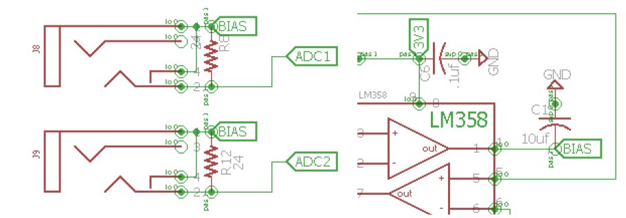
My impression concerning the impact on VT vs CT is opposite to yours. With the VT, the transformer is a voltage source, and as such will produce a current that is a function of the resistance of the circuit. IoTaWatt measures the voltage drop across a 1K resistor in that circuit as a proxy for line voltage. The voltage across that 1K resistor is a function of the current in the circuit. So the voltage sensed by IoTaWatt is directly affected by the resistance of the circuit, and the extention cable adds resistance. All that said, any added resistance can easily be calibrated out.
CTs are a different animal. The are a current source. Regardless of the resistance of the secondary circuit (within practical limits), the current is always the same proportion to the primary current. Doesn’t matter if I use 10 or 24 ohm burden, the CT generates the same current. So if you were to add .5 ohm to the circuit with extension cables, it should make no difference in the current loop or the voltage generated across the burden in the IoTaWatt. That said, you should be conscious of the possibility of introducing noise to these lines, especially where you are inside industrial machinery. Shielding or running inside metal conduit would probably be a good idea.
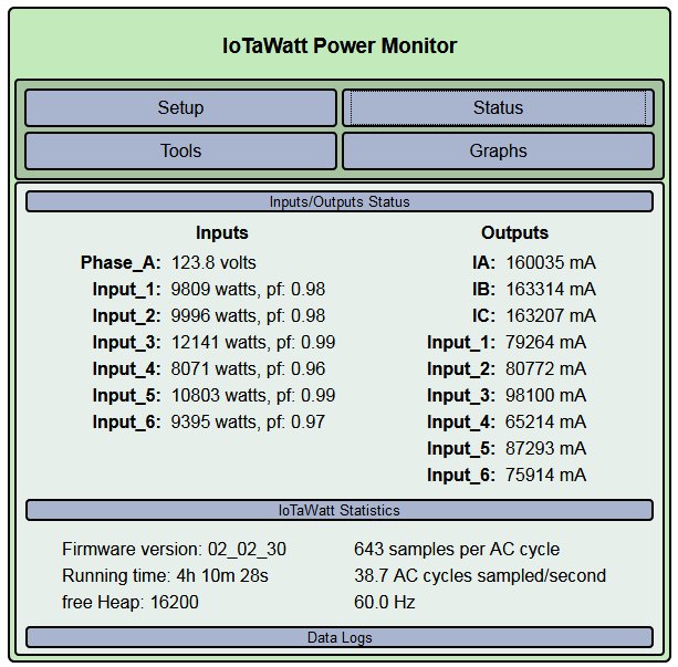
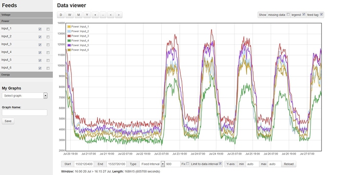
Beyond that, I do have an idea that you may want to explore. You say the current is carried in several parallel cables, and that you intend to put a CT on each and presumably add the power measured in each to get the total power. That should work fine, but maybe there’s a simpler approach: Lets say that you have three cables in parallel, each carrying a nearly equal amount of current. If you put a CT on each cable and wire the outputs in parallel, I think tyat’s the same as one big CT around all of the cables. In other words, you would only need one extension cable and one input on the IoTaWatt. I will try this on a smaller scale over the next few days.
The other thing I was going to ask is whether you intend to use the derived or direct method of three phase measurement. Regardless, this is an interesting project, and it would be nice if you coud document your experiences in the show-and-tell category of this forum.
I’ll be following along.
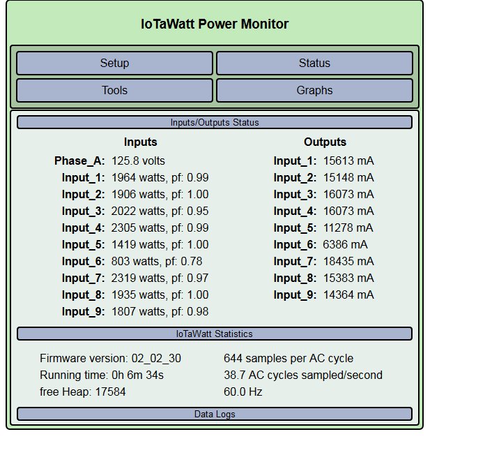
UPDATE: I tried connecting multiple CTs in parallel and it seems to work. Here I have three CTs in inputs 1, 2 and 3. They are identical CTs but each has a different primary current. The output sum123 is the total of the three.
input_4 is three more CTs connected in parallel, each clamped next to one of the inputs 1, 2, and 3. You can see that the power is the same as the sum of the individual CTs. (<.2%).
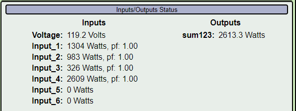
The inputs are all ECS1050 CTs (50A:50ma). The advantage here is that you can measure the sum of multiple circuits (or individual parallel cables in one circuit) using one Input on the IoTaWatt. The downside is that the total power cannot be more than the capacity of one CT, and all of the CTs need to be the same. So with the individual CTs on inputs 1, 2 and 3, the total current for the circuit could be as high as 150A, while the three combined cannot exceed 50A.
Depends what you want to do. Extending this to a more general case, I think that you could combine two or more identical CTs in a household panel using a simple stereo headphone splitter.


