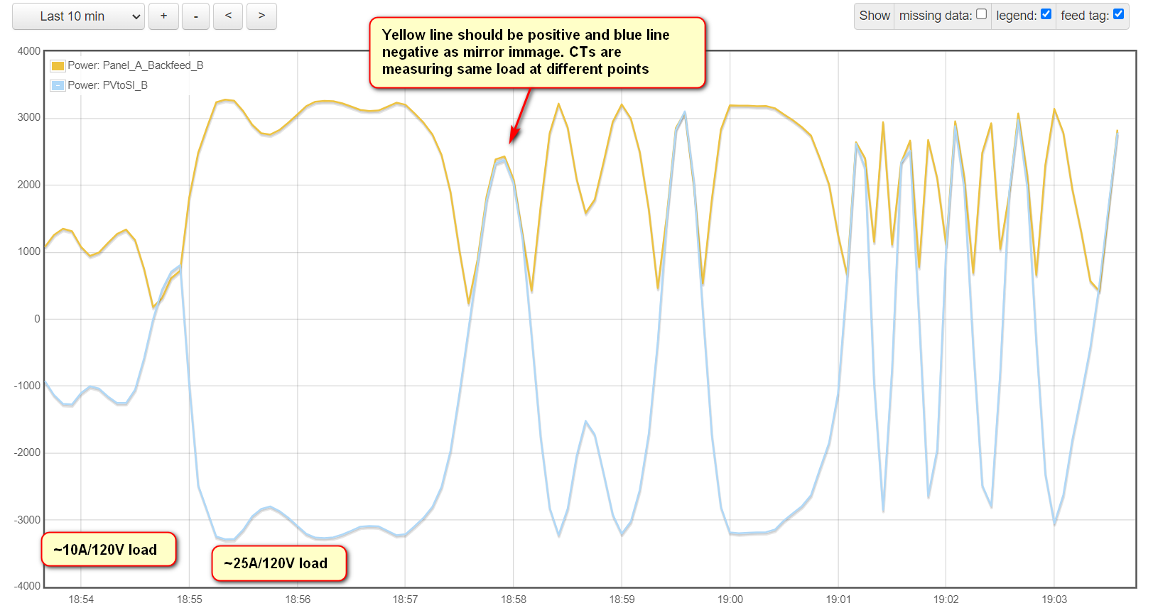
I purchased my Iotawatt system about 6 weeks ago and installed with no issues. I am in the US with a 120/240 split phase system. I have recently been integrating and testing a PV + Battery Inverter system which I am monitoring with this system. I have placed CTs on the AC input/output from the inverter and on the input to the panel (backfeed). The graph shows a negative value coming out from the inverter (supposed to, but not working as expected) and the other value is the power input to the panel. I expect there to be minor variations between the two readings, but I am getting very weird and unexpected readings.
I placed a clamp on multi-meter adjacent to one of the CTs to measure what was occurring. I measured a very consistent amperage and frequency on the conductor. The variance was no grater than 0.3A during the test and Frequency varied from 59.99 to 60.00. However the iotawatt shows large fluctuations in the current flow, power factor, and even flow direction.
The screen shot above shows the major fluctuations in the graph. During this same period switching over to the status screen these readings are varying from ~+3000w to zero to negative and back to positive and power factor is dropping from 0.98 down to very low (I saw numbers as low as 0.07) these numbers were rapidly changing during this process.
The CTs hooked up to the panel fed from the Utility power measures as expected with similar types of loads. This seems to be related specifically to the inverter supplied power. Power is from a pair of SMA Sunny Island 5048 hybrid inverters (one per phase). This was screen captured when the accompanying PV inverters were not producing any power, but I have seen similar results when power is being fed from the PV inverters Sunny Boy SB6000-US. These inverters are AC coupled and the backfeed to the panel in question is fed from a common panel that contains the SB PV inverter input and the SI Inverter Input/output.
I need a line drawing to be sure I understand what you are saying. You describe a pair of Sunny Island 5048 hybrid inverters and imply they are 120V. You also mention a Sunny Boy SB6000-US which is a 240V output inverter as far as I can tell.
I’m not clear on where the CTs are placed. I think they are probably measuring accurately because your graph shows the two traces exactly the same or opposite most of the time. The question is what they are measuring, what is not being measured, and what the load is if any.
To measure the mains power you need to add the 2 CTs. To measure the pair of hybrid inverters I would think you would need to also use 2 CTs and add the two. Your plot labels imply the two traces are only for one leg. I don’t think you can compare the two if there is any 240V load operating.
Overeasy,
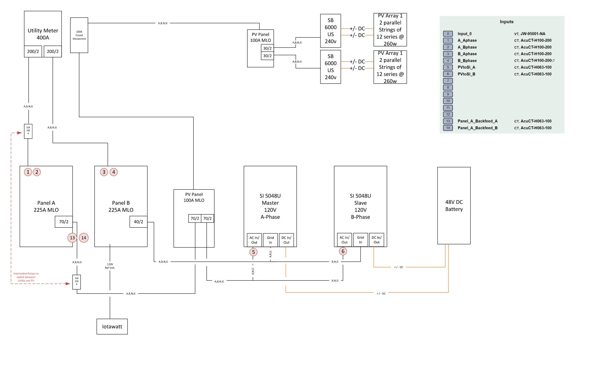
Thanks for your response. I have included a full diagram of my system and identified CT points. You are correct the Sunny Island are 120v Hybrid Inverters (one connected to A phase and one to B phase) and work together to create a 240v system input. The SB6000-US is a 240V inverter.
As I was updating my drawing to send to you I was thinking about the reference voltage and I’m wondering if this is what is causing the problem. The reference voltage is permanently connected to the B Panel (utility connected) while the CTs in question are connected to power connected from either Utility or Inverter (switched by industrial Solid State Relays and interlinked). The inverter and grid connection to the A Panel are never connected at the same time.
I will test this later today by using an extension cord to plug in the Iotawatt to a circuit from A phase panel. If this is correct then I would expect the metering on the inverter side to work as expected (not major variations in wattage and power factor, which are really not captured by the graph as it is 10-second data and the changes I am seeing are occurring rapidly), but then this would likely give me false readings on B panel CTs which are utility fed.
Is it possible to give multiple voltage references and assign them to specific CT inputs? What hardware would be required to accomplish this?
In the initial post the yellow line is CT 14 and blue line is CT 6. I am measuring at both points so I can determine how much PV is going to Inverter (and charging batteries or discharging from batteries to feed load) vs how much is going to feed loads in Panel A. When both meters all meters are positive a sum of the four gives me total PV production.
The Loads on Panel A are varied, many 120V residential loads, and the major load is a large A/C Unit compressor (about 3200w running/240v) and air handler (about 600w running/240v).
It’s definitely a factor here. Your Input_0 voltage reference is always the mains voltage. Panel A can be fed from either the mains or the PV panel, so when it’s on the PV panel, the voltage reference will not be correct, or even in phase.
I agree with that.
Absolutely. The IoTaWatt can directly handle up to three voltage references. One snag is that the additional two must use Inputs 13 or 14, and you are currently using those channels for your solar “backfeed”. I recommend moving those to lower input numbers ASAP as the history is fixed to the channel number and cannot be changed.
To add additional VTs, you simply plug into one of the three-phase jacks on the back and configure the channel as a VT. Be sure there is no CT plugged into the corresponding 3.5mm input.
Once you add an additional CT, all of the inputs will have an additional setup parameter called VRef. It will default to the channel 0 VT, but you can change it to any other VT. In your case, you would add a VT connected to the A panel and then select that as the Vref for channels 1 and 2 and the channels where you moved what is now 13 and 14. You would also use that Vref for any load that you measure off the A Panel.
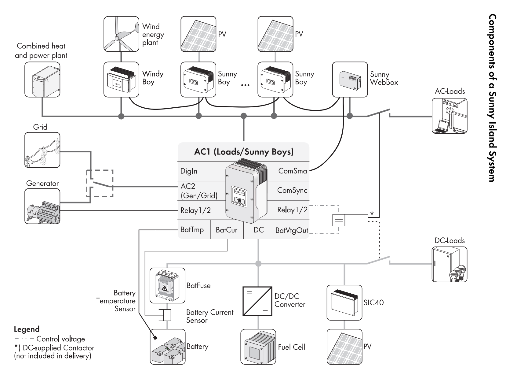
I’ll take a closer look at this later, but I do have questions about how the hybrid inverters work. I see that they have a “Grid in” from panel B, and also an AC in/out. Don’t understand yet how that works.
With some quick testing with an extension cord I did validate that having the reference voltage connected to the utility while measuring the loads on the ‘AC1’ side of the inverter (see pic above) was causing the crazy readings. I have ordered another 9vac wall transformer and believe this will be an easy fix once it arrives.