Grid tie inverter negative watts

Had to make a new account, was Jhorner000.

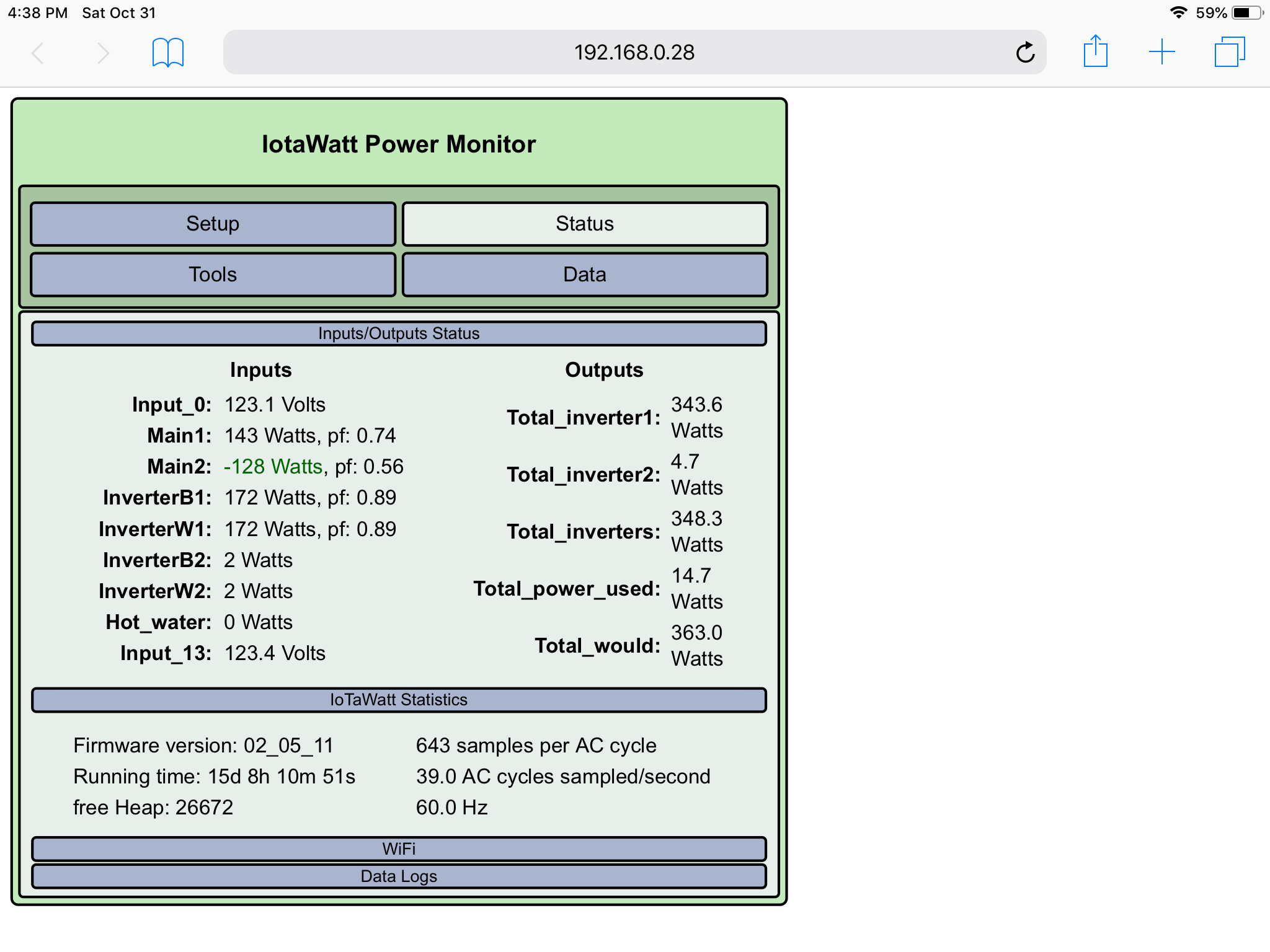
next pic is with allow negative values turned off Been using Iotawatt for a few years and I am very pleased. I check it everyday.
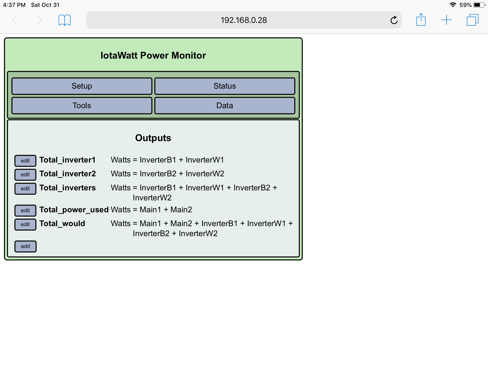
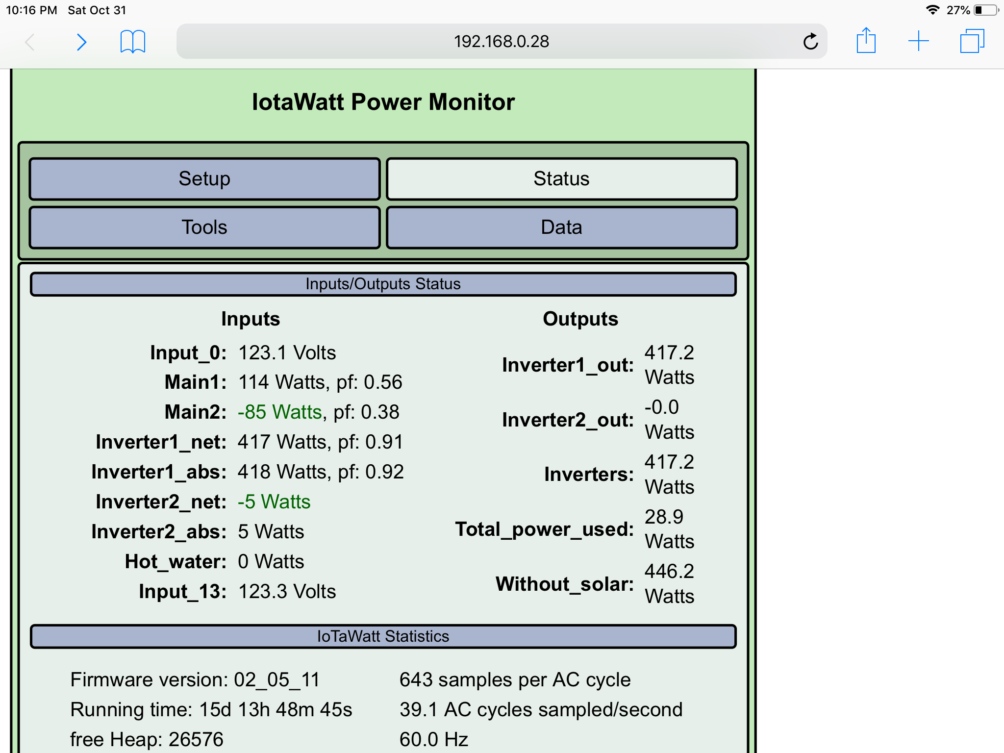
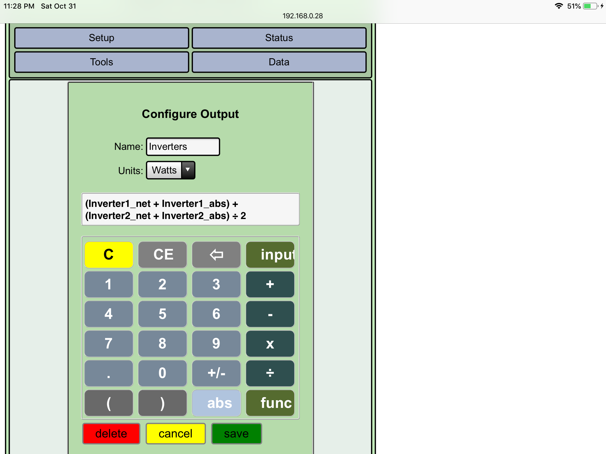
Question, when I select allow negative values for the ct on the inverter then the amount of power the inverter is using while the inverter at idle is shown as a negative. This makes sense because that’s power going into the inverter instead of out. But is also an issue because that negative amount is being deducted from the total that inverter is producing overtime. When I make an output that combines the watts of both inverters then the negative amount gets subtracted from the watts the other inverter is producing which isn’t giving a correct amount the inverters are producing.

When I turn off allow negative values (like in the pic) the amount the inverters use at idle is now positive as if the inverter was producing that amount which isn’t correct either.

Is there a way to make the Iotawatt correctly read the amounts the inverters are producing? I understand this idle amount isn’t much (7w Max) but adds up to incorrect data overtime.
Is there a way to make the amount the inverter shows for watts never go below 0? I have the mains monitored so I don’t need to see the amount the inverter is using from the grid. Thanks in advance for any help

I’m a moderator for a GTIL2 USA Facebook group. I have recommended Iotawatt to the group many times and I know of 3 members that for sure ended up purchasing it. No thank you required. It’s the least I can do for such a great device that is reasonably priced

I can see a way for you to do it. It’s very convoluted, and sorta unique to your circumstance. First let me reframe and expand on the problem slightly…

What’s at issue is adding up all of the positive power from the inverter, discarding the negative power going to the inverter. Because IoTaWatt accumulates net power, any attempt to do this at greater than 5 second grouping would begin to introduce error. The output

Inverter1Output = ( InverterB1 max 0 ) * 2

will add up all of the positive groups of InverterB1 .(The binary operator “max” selects the greater of it’s two operands, so when the value is negative, it yields zero).

If you plot this output in Graph+ to an hour’s worth of data, the grouping will be 5 seconds, so it will give you a good result. But if you run it over a day, the grouping will be 2 minutes, so the output script is applied to 2 minute net values. Where the 5 second values in a group are all positive or all negative, the result will be correct for that group. Where they are mixed, it will be incorrect because the script only operated on the net value.

That might not be a problem in this case, because my sense is that the overwhelming amount of negative values would be at night and the positives during the day. There may be some mixup during startup and shutdown, but that would be insignificant.

The problem starts to grow as you zoom out to a week or month and the groups become larger. You need an approach that integrates over the individual samples. IoTaWatt doesn’t do that, it would be too resource intensive.

So now the convoluted solution. For some degree of simplicity I’m going to only show this for one inverter.

You currently have two CTs on the inverter, one on each of the wires, but this is a two wire appliance so only one is needed. That is key to this solution. So lets reconfigure the two CTs as:

Inverter1_net where you check “double” and “allow negative values”
Inverter1_abs where you check “double” and NOT “allow negative values”

This essentially performs the data segregation as each sample is taken.
Let’s restate those two inputs in terms of Pout, the power generated, and Pin, the power consumed.

Inverter1_net = Pout - Pin
Inverter1_abs = Pout + Pin

Now if you add the two together you get 2Pout. Dividing by 2 you get Pout, So defining an output:

Inverter1_out = (Inverter1_net + Inverter1_abs) / 2

Should give you what you are looking for, the positive output of the inverter… And it follows that an output:

Inverter1_in = ( Inverter1_net - Inverter1_abs ) / 2

Will give you the amount of power the inverter consumes as a negative value.

2 Likes

Ok I’ll give it a try. So I should rename the CTs going to one inverter?
Inverter1_net = Pout - Pin
Inverter1_abs = Pout + Pin
Or should they be named?
Inverter1_net
Inverter1_abs
And then create an output?
Inverter1_in = (Inverter1_net - Inverter1_abs) / 2
Is the spacing critical?

And then do the same for the other inverter?

Yea, that’s it. The spacing is what the calculator will do when you enter the script.

The scripts will not work on historical data. They will only produce useful results with data from after you reconfigure the inputs.

1 Like


Done. It works. Thanks a lot overeasy.


Would this be the correct way to configure the output so I can see what both inverters are producing combined?

( Inverter1_net + Inverter1_abs + Inverter2_net + Inverter2_abs ) / 2

This is equivalent to your script the way they are currently evaluated, because operators are evaluated left to right. That was a mistake, and going forward I intend to transition to conventional operator hierarchy. When that happens, the above notation will evaluate differently. When the switch is made, scripts will be altered with parenthesis to reflect the pre-transition hierarchy so that they will continue to produce the expected result.

1 Like

Interesting. Being a new user and not being sure how the max function worked I created an output with the expression (Solar_PV abs + Solar_PV) ÷ 2 to get the same effect, where negative values would be treated as zero. The input Solar_PV represents a single CT with the ‘double’ and ‘allow negative values’ option checked. I hadn’t thought about the issue of accumulating net values over time and errors that could be introduced in the graphs/reporting. Is there any way this scenario can be addressed in the firmware of the IoTaWatt in a future release so as not to require the “2 CT solution” described above? Just wondering. Not a crisis. :slightly_smiling_face:

The problem is that there is no place to accumulate the result. I’m faced with the same problem accumulating Varh in that it needs to be an integration and the datalog has no space to save it. Both can be exported and maintained in an influx database. The native solutions would be to create an additional log or expand the existing log.

Expanding the existing log is problematic because it would involve creating a new log before deleting the old. Some of the older units only have a 4GB SD card, so not enough space. Besides it would take a looooong time to do in the background. Not impossible, but very risky.

Creating an additional log where there is enough space would be possible. I actually have a branch that does it, but queries using that data would be quite a bit slower and require more working heap.

This is part of a recurring theme where further development is increasingly inhibited by the capabilities of the ESP8266. The ESP32 prototype has a huge datalog and is fast, but I can’t get there from here if I keep working on major enhancements to the ESP8266.

I vote for the ESP32 and I already have two of the ESP8266 based ones (both v4 hardware). I assume it is likely to be at least a year before an ESP32 based one is likely to come out.