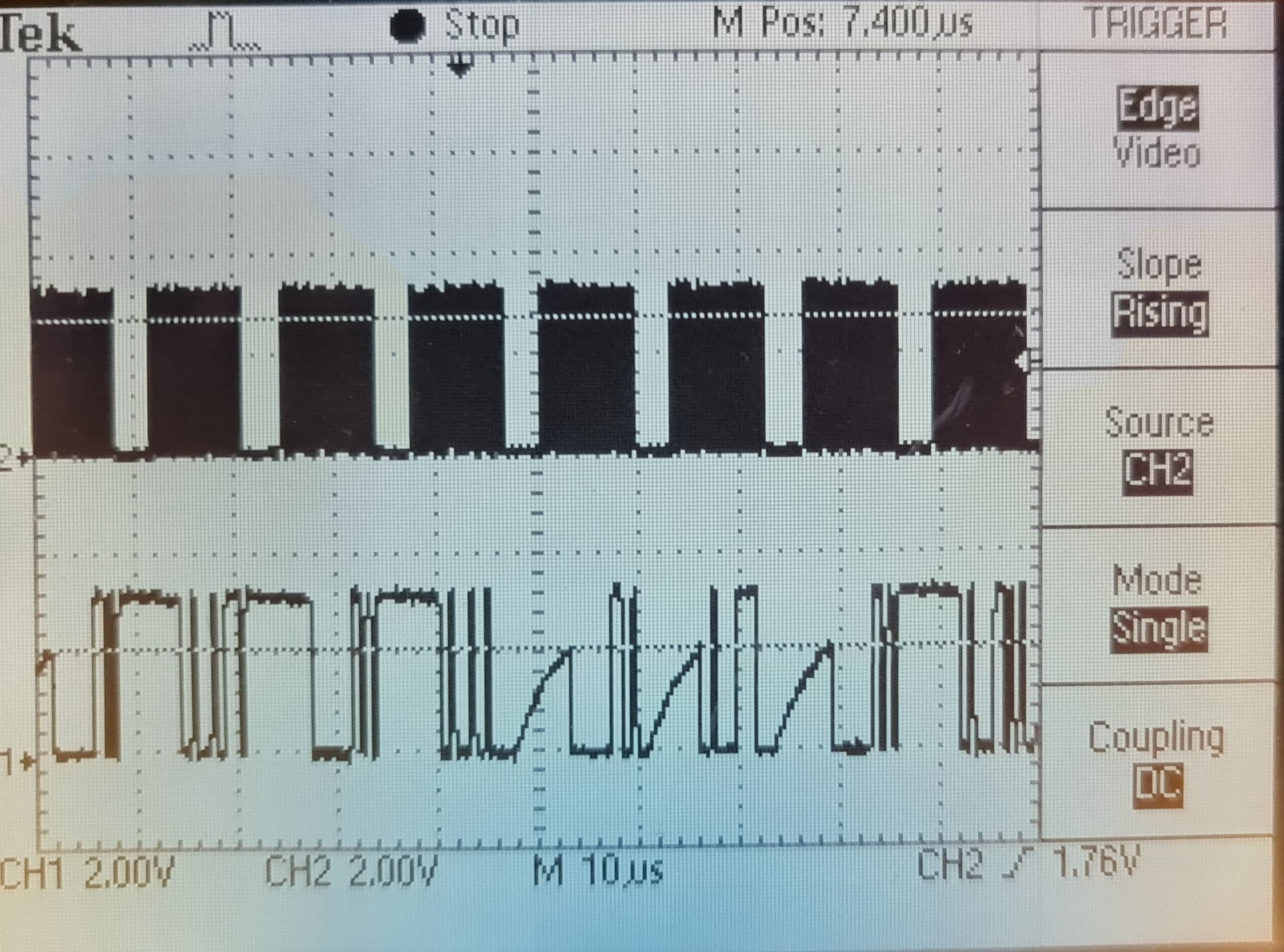
Hardware diagnostic - dead NodeMCU

Hi community.
I just installed my iotawatt unit a week ago but it died. First all the redwings went to zeros, and when I took out of enclosure to my desk and powered up then it died completely - no LED.
I checked the USB cabling and voltage all OK. The 9V AC is ok as well.
I have the rev 5.0 board. The AMS 1117 regulator onboard of the NodeMCU is heating up and the output voltage is about 1.1V instead of 3.3.

  • The main board with the NodeMCU removed draws 1.7-2.0 mA @3.3V is that expected current? I have quick look trough the component ds but could not find anything that would draw such a current…
  • The board is using AMICA NodeMCU with ESP12S is there alternative?
  • I will need to get new NodeMCU dev board any pointers to reliable supplier especially in Australia?

Maciej

There are two separate functional issues described here, and a third procedural issue.

First are the measurements going to zero. Typically, that is caused by a problem with the voltage reference. While there can be several different causes for that, it is usually a pretty straightforward path to resolution. Suffice to say that if you are getting zero readings using the status app, the nodeMCU and related hardware are working fine.

The second problem is described as the unit dying completely. In my experience nodeMCUs are like Timex watches. They take a licking and keep on ticking. While I don’t discount that one could go bad spontaneously while in service, I am dubious in this case. I don’t believe in coincident unrelated problems. As explained above, the nodeMCU was running fine at the time of the first problem. It’s not clear what transpired between the first and second problem, but at some point, the PCB was removed from the enclosure and powered up outside, then apparently the nodeMCU was removed.

This brings us to the third procedural issue. Folks, these things don’t often fail, and most of the time it’s a simple matter to get going again. In this case I’m being presented with a basket case that is beyond any reasonable point of salvage. Please, please, please, give me a shot at diagnosing and correcting field problems before you try indiscriminate solutions, especially where they involve screwdrivers and soldering.

This unit is an Aussie unit. Because Australia has a unique plug type and because it cost a lot to send heavy power supplies halfway around the world, I recommend locally available power supplies and VTs Unfortunately many do not recognize the difference between a USB power port or charger and a quality USB power supply. They just use an old phone charger or wall socket USB port to power their IoTaWatt. Best case is it introduces excessive noise or WiFi instability, worse case is you fry the nodeMCU. Not saying that’s what happened here, but I did ask and received no answer.

I have not measured the main board current draw but can easily compute that the .voltage reference shunt circuit draws about .7 mA and the bias circuit voltage divider draws about .3 mA So that’s 1 mA. Add to that the draw of the RTC and SDcard and 1.7-2mA doesn’t seem unreasonable. The LED alone will draw much more than that when on. The power supply on the nodeMCU is capable of providing several hundred mA. So I think that whole line of investigation is a red-herring. The most likely cause of the regulator overheating when brought to the bench is that it was damaged by a malfunctioning or inappropriate power supply.

The nodeMCUs used in IoTaWatt are custom made and tested. ESP12S nodeMCUs are hard to find but used because of their specific FCC part B compliance. Aside from that, any ESP12E should work.

Thanks for extensive reply :slight_smile: !

  • The AC reference I used is the recommended Powertech supply. I checked the output with oscilloscope. Visually it look like clean sinus to me. I do not remember the voltage but it was close enough to 9V
  • The USB power supply was phone charger.
    • The ripple/noise under ~100mA load is less than a 5mV, so I would say good enough PS.
    • Checked the powerup sequence with quality oscilloscope.
      • No spikes during connection or disconnection.
      • The power up curve is nice and smooth, I think there is substantial cap on output.
      • I was not able to trigger the DSO above 5.1V with connecting and disconnecting from 240. Sorry I did not take any screen shoots from DSO someone took the data cable from lab…
    • Not sure about filtering out noise from mains, that bit difficult to test. In general I do not have problems with noise in my house.

As the power supplies are not likely problem I went back to the electrical enclosure and I think I found the problem. The power socket in electrical enclosure is bugged. Most likely it was arcing, there is broken plastic peace and one of the poles socket was loose.

The reason I ask for the current of board without NodeMCU is to get rough estimate if there is damage to any other components. It looks like 2mA is expected so no obvious damage there. I wonder if the arcing destroyed the ADC chips… will see. I ordered NodeMCU replacement. Managed to find one in AU: https://makerzone.com.au/product/esp12-dev-board/
Will continue after it arrive.

I am not familiar with the NodeMCU and the firmware. Will it flash initially from SD or I need to flash it separately? I think someone mention platform.io as IDE for this project?

ADCs are pretty robust. Most probably fine. You will need to flash the esp. Firmware is on GitHub. If you Google esptool you will see how to flash with that. The .bin firmware file for each release is on GitHub.

1 Like

Ok, the NodeMCU arrived today. Reflashed it and it works.
Still all values are zero. I do not have CT probe available on bench so relying on AC ref.
Input looks bit excesive 29V peak to peak that’s 10.25 rms:


It is from MP3027 transformer.

After the divider it seems to be clamped a bit by diodes:


I think the diodes clamp at 1.2V that will introduce non linearity in voltage measurement… but it is different story.

I think one of the ADC is bugged. Here is the clock and one of the data lines (I think MISO but not quite remember):

Interesting: the protective diodes are ok so I assume the noise went trough the 5V supply and NodeMCU. It seems unlikely to me… still missing something here…

Will order new ADC and report.

Occam’s Razor.

The more you replace components without understanding how they are intended to work or how they relate to any perceived problem, the more likely you will introduce new problems.

The voltage output from the MP3207 is normal. You might try simply plugging it into input 13 or 14 to see what happens. Those inputs use the other ADC and completely different TVS diodes.

OK,
That bit put me off:


But maybe it is floating line when CS is not active? anyway…

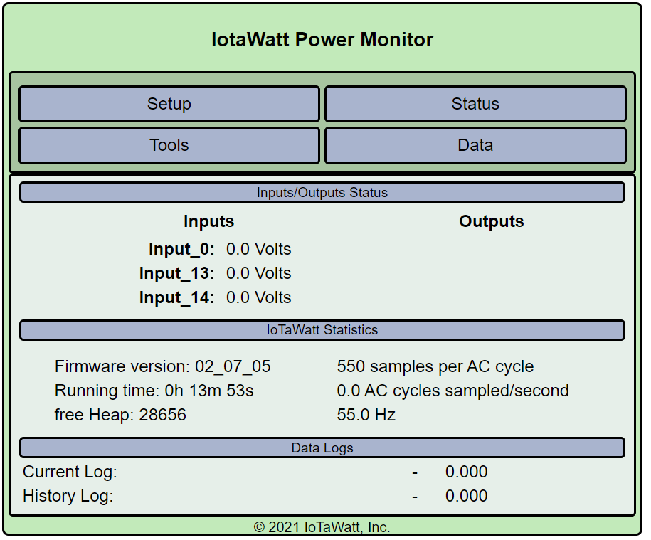
I wiped the config and started from scratch. I configured channels 0,13,14 as VT with MP3027.
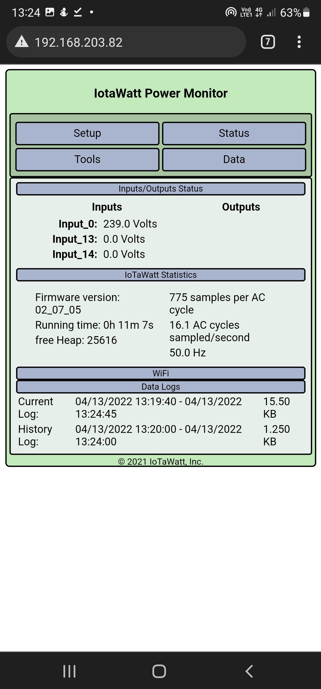
Still all zeros (I tried all 3 inputs):

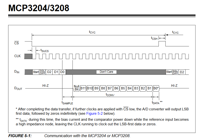
Once the 13,14 are configured as VT I notice trace statement in log:

** Restart **

SD initialized.
3/31/22 10:37:28z Real Time Clock is running. Unix time 1648723048 
3/31/22 10:37:28z Reset reason: Software/System restart
3/31/22 10:37:28z Trace:  1:2, 1:3, 1:3, 1:1[13], 1:2[14], 9:0[14], 9:0, 8:4, 8:2[14], 8:2[14], 1:2, 1:3, 1:3, 1:1[14], 1:2, 9:0, 9:0, 8:2, 8:2, 1:2, 1:3, 1:3, 1:1, 1:2[13], 9:0[13], 9:0, 8:2[13], 8:2[13], 1:2, 1:3, 10:2, 10:3
3/31/22 10:37:28z ESP8266 ID: 14700508, RTC M41T81 (68)
3/31/22 10:37:28z IoTaWatt 4.x, Firmware version 02_07_05
3/31/22 10:37:28z SPIFFS mounted.
3/31/22 21:37:28 Local time zone: +11:00
3/31/22 21:37:28 device name: IotaWatt
3/31/22 21:37:28 HTTP server started
3/31/22 21:38:32 Restart command received.

** Restart **

SD initialized.
3/31/22 10:38:33z Real Time Clock is running. Unix time 1648723113 
3/31/22 10:38:33z Reset reason: Software/System restart
3/31/22 10:38:33z Trace:  8:2, 1:2, 1:3, 1:3, 1:1, 1:2[13], 9:0[13], 9:0, 8:2[13], 8:2[13], 1:2, 1:3, 1:3, 1:1[13], 1:2[14], 9:0[14], 9:0, 8:2[14], 8:2[14], 1:2, 1:3, 1:3, 1:1[14], 1:2, 9:0, 9:0, 8:2, 8:2, 1:2, 1:3, 10:2, 10:3
3/31/22 10:38:33z ESP8266 ID: 14700508, RTC M41T81 (68)
3/31/22 10:38:33z IoTaWatt 4.x, Firmware version 02_07_05
3/31/22 10:38:33z SPIFFS mounted.
3/31/22 21:38:33 Local time zone: +11:00
3/31/22 21:38:33 device name: IotaWatt
3/31/22 21:38:33 HTTP server started

Any ideas?

Have you checked the Vref and bias voltages? Your scope of the signal coming off the voltage divider in the input (12K/1K) does not appear to be biased.

The SPI transaction is described in the MCP320x datasheet:

There should be 19 clock cycles. The data (MISO) is clocked out in the rightmost 12 bits (cycles). Here is a cycle with data of 2048 0800h (biased zero reading).

Here is a reading of 2046 07feh, very close to a biased zero.

and here is a reading of 1629 065dh .

Understand that the SPI also services the SDcard, so not all transactions are ADC, although the vast majority are. Also, the MISO line is not defined except during the 12 bit data clockout, so you can see it high or low between transactions:

From multimeter
Bias measured on C2 is +7.5 mV from GND
Vref (I assume VREFF net on schematics) GND->PIN5 of LM358 : 6.1mV

Again for reference the signal on divider with respect to GND:

Time to go to work… pesky thing but one must earn money to spend on unnecessary components :wink:

Vref should be about 3.3V and the bias should be half of that. The biased AC signal should be completely positive with respect to ground.

Voltage on the opamp chip with respect to GND
1: 6mV
2: 7 mV
3: 5 mV
4: 0 V
5: 0 V
6: 3 mv
7: 0 V
8: 3.263 V

I disordered the opamp and the divider R1,R2 work as you described about half of 3.26 V on pin 3.
After disordering the chip the BIAS is floating (resistance GND->BIAS and BIAS->3.3V). I use ohmmeter, it is low initially and then increases to Mega ohms range. I assume that’s capacitors charging in.
I assume opamp is busted? If that’s the case what chip you using?
I found those LM358AMX and LM358MX did not have time yet to figureout what the “A” stand for…

On a side note I notice the output of the R1/R2 divider is called VREF, bit confusing…

The culprit


The little broken out pieces went inbetween the contacts and made them permanently open so the connection was intermittent.

A mechanism to cover one of the holes until you plug it in. The hole that is covered is neutral :slight_smile: :grin:

2 Likes

It is alive!

Just received the opamp LM358DR2G and replaced it. It measures the voltage yay! Will do some more tests in later on.
Maciej

1 Like


All seems to be working OK!
:man_dancing: :man_dancing: :man_dancing:
In summary:

  • I think the opamp died because the bad power socket arcing
  • the NodeMCU died on bench, I must have shorten something.

@overeasy first thanks for your support! Second question/suggestion. There is one spare port on the protecting diodes. Would it be possible and useful to use it for the ACBIAS or add another set of diodes for the other BIAS?

For Australian friends looking for NodeMCU locally: https://makerzone.com.au/product/esp12-dev-board/