Hello,
I am located in Ontario, Canada. I have had iotawatt running for about a month, and also a new heat pump running for about 6 weeks.
Heat pump is using a 2 conductor 10awg on a 30amp double pole breaker. Also, there is a 15kw 2 stage electric heater backup (7.5kw +7.5kw) installed on a separate 100amp breaker.
iotawatt is installed on the heat pump using one 50amp CT clamp and “doubled” in the input setup. and a 100amp CT clamp on the electric heater breaker, doubled in iotawatt.
Data has been consistent up until yesterday.
The unit has been drawing between 2300w-2500w at temperatures around -5C to 10C since installation.
Yesterday, it was cooler, around -10C. Thermostat was turned up from 68F to 70F and the power consumption climbed up to 7300w on the heat pump breaker (electric heat backup still reading 0w or 1w). This would be around 29 or 30amps which is maxing out the breaker capacity which is not ok. From my understanding breakers should only be loaded to about 75% capacity. so this is a safety issue, assuming my iotawatt is setup properly.
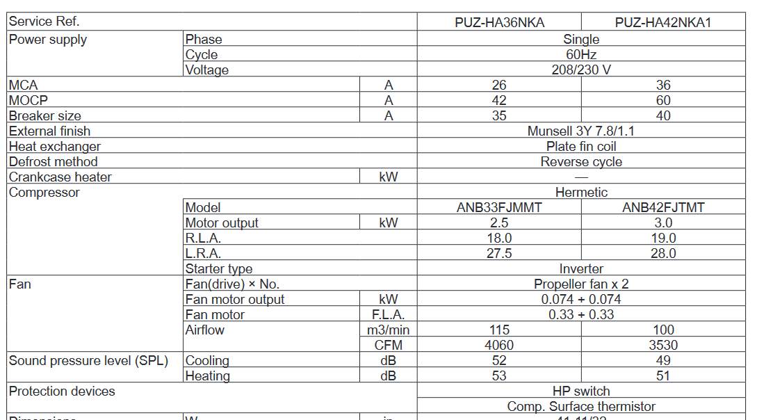
Max wattage according to the manufacturer is 4895w.
All this being said, before I call the contractor back to confirm the electric heater is hooked up to the separate 100amp breaker properly (and not being powered improperly from the heat pump breaker) is there something I am missing in configuration of Iotawatt? maybe I should monitor the 240v heat pump conductors with separate ct clamps instead of doubling in the software?
The Minimum Circuit Ampacity (MCA) is rated at 26. That equates to about 6,240 Watts at unity PF. The Specs call for a 35Amp breaker.
I didn’t see any reference to heat strips in the specs and nothing in the Mitsubishi schematics. Are they inside the inside unit(s)? These may be an add on by the rebranding company.
Looking at it from a practical side, 2,300W-2,500W is not very much for a unit designed to output (10.5kW (36,000BTU). That would be a COP of 4.2, which I would not expect at -10C. Zuba puts it in the low 2’s at that outdoor temp. So, I would expect power to go up significantly at lower COP when demand is for full capacity, which may be the case when you boosted the thermostat.
The schematic shows an optional base heater which you probably have. I’m in a more temperate zone and had to add one to my Mitsubishi unit to prevent icing in those conditions. My base heater is 150W but your outdoor unit is a lot larger so may add substantially more.
Regarding one or two CTs, the Mitsubishi wiring diagram shows two-wire, so that would be OK. Nevertheless, you should check that Zuba has not added anything to the circuit and specifically something requiring a neutral connection.
Thank you for the reply. Yes the unit is a mitsubishi zuba Sorry should have been more clear. The specs for the unit are shown on page 9 of the pdf. The electric heater is an addon option from Mitsubishi that is installed in the indoor unit. It supplements heat when outdoor temps get too low for the heat pump to keep up. The MCA you show is the same as the document I posted, so yes it looks like the breaker is undersized.
EDIT: looking further at the document, indoor and outdoor MCA are seperated, and total 31.5amps. Because the indoor unit is powered from the outdoor unit my breaker is definitely undersized.
Unfortunately I do not have faith in the contractor as they did not seem knowledgeable during the installation so I am just trying to make sure the heat pump is installed properly and wiring/breaker size is sufficient for safety reasons.
So it appears iotawatt is configured properly, I guess I will have to give the contractor a call and see what they say about upgrading the breaker and potentially the 10awg wire going to the outdoor unit.
If you have any other suggestions please let me know. Thank you very much.
If you increase the breaker size, you definitely need to increase the wire size. Based on the data you collected, it seems like it would be a very good idea to increase the breaker and wire size. How much you need to increase the wire size depends on how long the wire is.
For my 2HP well pump, I used 6ga wire to keep the voltage drop down even though the pump only typically uses about 12A. Of course, that is because the pump is several hundred feet away from the house.
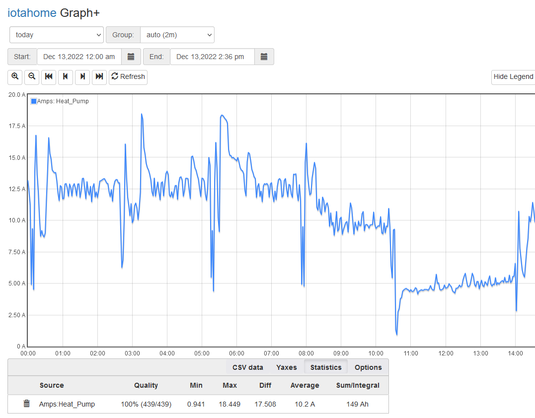
It might be worthwhile to plot Amps for that circuit with Graph+ over a day to see if high loads are transient and what the steady state seems to be at various outdoor temps. I know my heat pump spikes coming out of a defrost cycle and it has a 15A breaker (one ton).
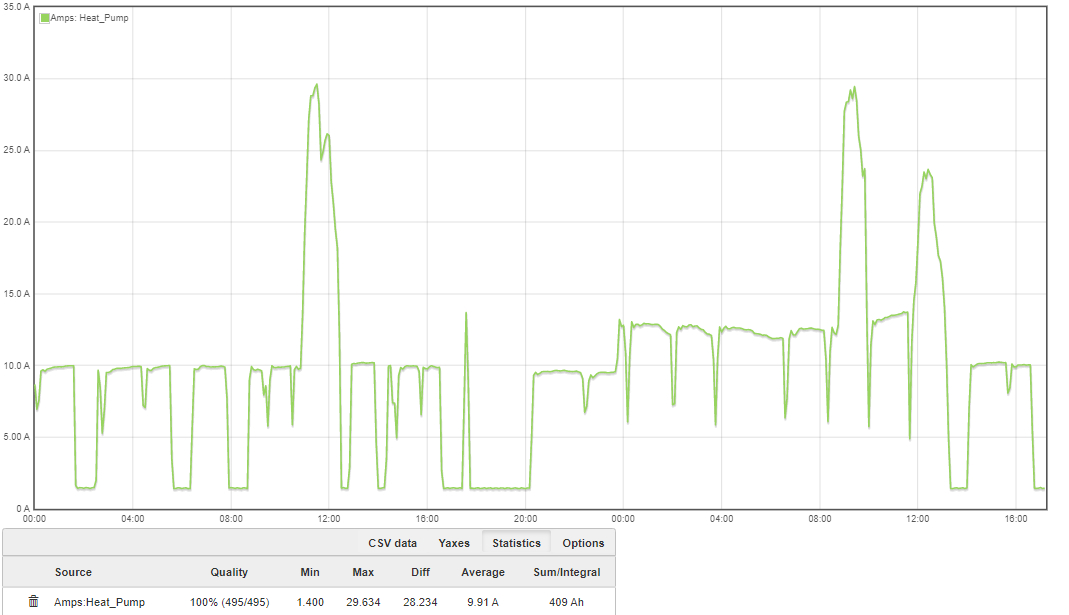
Here is my amp graph over 2 days. this is the first time seeing this large of an amp draw so far, which raised the flags for me knowing the circuit was only 30amps
I don’t have any experience with a whole house heat pump, but have looked at the draw of my heat pump water heater quite a bit. Your graph looks unusual.
I suspect you have an extra load of about 15A that is being turned on for some reason. Perhaps your strip heaters are not wired correctly?
I believe it is working correctly, but you could be right. The contractor is coming back Thursday to upgrade my breaker and wire so hopefully the tech coming this time is a bit more knowledgeable. Once that part is fixed im probably going to have to pay a 2nd contractor to come out to check over the unit and ensure it is connected and configured properly. There are a lot of settings in the unit and I would guess this contractor has not adjusted or checked it properly.
It is very hard to get a knowledgeable hvac contractor in my area that specializes in heat pumps. Heat pumps are only now becoming more common so nobody has extensive knowledge with them.
The graph period is 40+ hours so each datapoint(Group) is the average for Watts for that 5 minute period. Where you are looking for peaks, you can zoom into a smaller time frame by selecting the period on the graph with the mouse.