I am running in to an issue where I cant see if the Iotawatt reported power-factor for a channel is leading or lagging.
I have enabled negative power for the channel and it doesn’t help.
Ideally I would be able to see if the power factor is leading or lagging, and/or better yet allowing for a negative var value when the pf is leading.
I have a situation where my var is 10kva(always +), and I switch in a 17kvar (leading) capacitor and the var changes to 7kva. It should be -7kva. I have verified that when the var is 50kva switching in the capacitor changes the var to 33kva, so the readings are correct and it seems that the Iotawatt cant report (or tell) the signed PF. Is there anyway to solve this? Script change or new firmware?
Thanks!
This has never been brought up. I will look into it.
Not being a power engineer, and after looking at the overview of the theory and how some others work, I don’t see how I could do this.
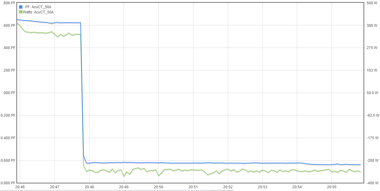
Power factor is simply real-power/apparent-power or Watt/VA. That’s how IoTaWatt does it, and the sign is negative when real power is negative as when excess PV power is exported through the mains. In looking into this, I’ve discovered that the sign is not shown in the inputs status display, however if you create an output with units PF the value displayed in the outputs status will show the negative value when that is the case. Another issue is that when graphing in graph+, the value is negative but the legend does not sign the scale:
Query will return negative PF when real-power is negative.
Leading and lagging PF appears to be something different, and a separate attribute. I’m not clear on how I would determine that without getting into something like FFT, which is not feasible with the ESP8266 and probably over my head anyway.
IoTaWatt calculates VAR by solving the “power triangle”
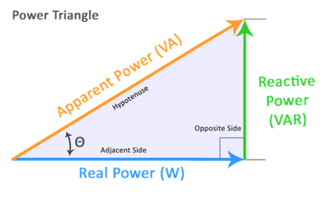
Specifically it calculates
VAR = \sqrt{VA^2-W^2}
So, mathematically the solution is positive given that VA >= |W|
I can and will fix the negative PF reporting problem, but that will not resolve any of your issues.
I wonder if I still have any credibility here? 
If I set up a channel to just measure one thing, and it’s a highly inductive load, I get positive watts. (the load is an old transformer based wall wart, with no load on it. And the iotawatt channel is set up to read negative power.)
If I then unplug the power supply, and plug in a highly capacitive load, I get negative power. (the capacitive load is in fact a capacitor.*** Since I’m not generating any power, this is clearly wrong. On the other hand, it seems to indicate that the iotawatt can tell the difference between a leading and a lagging load.
Also, wandering about on the internet, there seems to be a lot of confusing about positive and negative power factor. I think some of this might be confusion between leading and lagging current, which is not the same as power generation vs power consumption. A power consuming device can have leading or lagging current. I think that VA is always positive by definition, but some meters display leading and lagging as +/-, which might be the source of some of the confusion.
***Don’t plug a capacitor into 120vac if you don’t know what you are doing, as some of them will explode. You need to use a motor run capacitor, not a motor start capacitor. And even though I used a motor run capacitor to do this, I still tested it first on a cement floor with a steel box over the capacitor. It did not explode or heat up, thus it was safe to use for this.
I suspect there are power quality meters that can tell all sorts of things including information about harmonics and yes, leading or lagging current. I believe those devices cost much more than IoTaWatt and are typically dedicated to a single load.
I’m guessing that the negative power observed in your capacitor experiment is single digit Watts. Most commercial meters have a starting current below which they do not work. I have some EKM meters like that. I’d be surprised to see a significant load show negative. IoTaWatt doesn’t show PF below 60 Watts because the phase shift and signal to noise ratio of the CT at very low current are highly variable.
VA is the product of two RMS values which cannot be negative. The signal has both negative and positive components but the RMS calculation removes that sign when the samples are squared.
You are correct in that the power levels were quite low, around 6 watts the first time. So I redid it with larger capacitors.
I used six 6mfd caps, so a total of 36mfd. I also used a 20 watt soldering iron to supply a purely resistive load for some of the test. This contraption was hooked up to a single channel on the iotawatt, but with 11 turns thru the current transformer.
Running just the caps, I get a current of 18.3 amps. VA is 2.25kVA. Watts are -55. VAR is 2.25kVAR. PF is .024. The current and the VA are both about what one would expect with 36mfd and the 11:1 on the current transformer.
Running just the soldering iron, I get 267 watts, 266 VA and the PF is .999. So it looks like the soldering iron is more like 24 watts, but other wise these all look correct.
Running both the soldering iron and the caps at the same time- Watts is 211. VA is 2.26kVA. Power Factor is .093.
All the readings were rock solid, no noise or jitter. Most of the readings seem to make sense except the watts when running both the soldering iron and the caps. When I added the caps the existing load from the soldering iron, the watts went down, from 267 to 211. This should not happen. It should be going up by 56 watts, not down, since the caps do draw at least some real power.
I realize that you said this should not work. But the iotawatt appears to be able to read capacitive (leading?) reactive power, but then does not process it correctly. Like maybe there is a sign flipping when power switches from lagging to leading. Or it’s just reading absolute values. But it does seem to measure the current correctly, even when it’s leading by a lot.
Given that there are almost no cases of leading power in the world, I’m not sure if this really matters to most people. But tt would be good to see leading vs lagging for someone who is setting up power factor correction, since you don’t need/want to over-correct.
Cheers for the investigation and some great points!
The open energy monitor project has some great info and graphs demonstrating these concepts An Introduction to AC Power — OpenEnergyMonitor 0.0.1 documentation
It looks like the ADC routine measures the current and voltage over a set number of cycles to compute real power rms, and that the apparent power is RMS Voltage * RMS current.
These approaches are sound for linear/ideal loads with sinusoidal currents and voltages, but for non linear loads (Apparent Power)2 = (Real Power)2 + (Reactive Power)2 no longer applies therefor VAR=±√(VA2−W2) also is not true.
But given that we are working with an esp8266 and understand the limitations of the data it produces it does leave the question on how to compute the ± ambiguity.
If you have enough time base data, most solutions for determining leading or lagging for a mostly linear load look at the timing of the zero crossings, the peaks of current or instant power vs voltage peak. The old CIVIL initialisim helps here!
Apparent power, VA can be signed but computing it from rms values will always result in a positive value and the sign inferred from the power flow direction.
Reactive power VAR is signed and its sign depends on the leading or lagging of the power factor, Where positive var reffers to a lagging PF.
I have seen PF shown as .95i or .95c.
Phase angle is signed and the math follows nicer .95i = 18.2° .95c = -18.2°
Negative powerfactor is a bit of a misnomer, were it really only represents the power factor of reverse power flow.
I would record the Vindex position for max and min rawI and rawV across a few cycles and compare to compute the sign.
The distance between them should also roughly line up with the calculated pf so that could be used as an input or sanity check.
It might get noisy near 0 var so a longer averaging window could be useful and/or you could use the same 60w cuttoff mentioned for PF.
My use case is for setting up PFC and not over/under shooting to avoid additional charges. Which is why I was scratching my head for a bit!
Actually, the best way would be to do a 90° phase shift on the voltage, then use that to calculate the Instant var. The algorithm for the virtual phases is already there. And it is automatically signed.
See the simulation below for reference. It could be made available as VAr Phase shift, or VAr Instant.
| Vrms | 247.4873734 | 2.121320344 | 247.4873734 | |||||||
|---|---|---|---|---|---|---|---|---|---|---|
| Peak | 350 | 3 | 350 | |||||||
| Phase shift | 0 | 20 | -90 | |||||||
| deg | v | ic | V90 | Instant power | Instant var | V^2 | i^2 | |||
| 0 | 350 | 2.819077862 | 2.14401E-14 | 986.6772518 | 6.04413E-14 | 122500 | 7.947199994 | |||
| 20 | 328.8924173 | 2.298133329 | 119.7070502 | 755.8386259 | 275.1027617 | 108170.2221 | 5.2814168 | |||
| 40 | 268.1155551 | 1.5 | 224.9756634 | 402.1733326 | 337.4634951 | 71885.95088 | 2.25 | |||
| 60 | 175 | 0.520944533 | 303.1088913 | 91.16529328 | 157.9029198 | 30625 | 0.271383206 | |||
| 80 | 60.77686218 | -0.520944533 | 344.6827136 | -31.66137409 | -179.5605752 | 3693.826977 | 0.271383206 | |||
| 100 | -60.77686218 | -1.5 | 344.6827136 | 91.16529328 | -517.0240703 | 3693.826977 | 2.25 | |||
| 120 | -175 | -2.298133329 | 303.1088913 | 402.1733326 | -696.5846456 | 30625 | 5.2814168 | |||
| 140 | -268.1155551 | -2.819077862 | 224.9756634 | 755.8386259 | -634.2239122 | 71885.95088 | 7.947199994 | |||
| 160 | -328.8924173 | -3 | 119.7070502 | 986.6772518 | -359.1211505 | 108170.2221 | 9 | |||
| 180 | -350 | -2.819077862 | 2.14401E-14 | 986.6772518 | -6.04413E-14 | 122500 | 7.947199994 | |||
| 200 | -328.8924173 | -2.298133329 | -119.7070502 | 755.8386259 | 275.1027617 | 108170.2221 | 5.2814168 | |||
| 220 | -268.1155551 | -1.5 | -224.9756634 | 402.1733326 | 337.4634951 | 71885.95088 | 2.25 | |||
| 240 | -175 | -0.520944533 | -303.1088913 | 91.16529328 | 157.9029198 | 30625 | 0.271383206 | |||
| 260 | -60.77686218 | 0.520944533 | -344.6827136 | -31.66137409 | -179.5605752 | 3693.826977 | 0.271383206 | |||
| 280 | 60.77686218 | 1.5 | -344.6827136 | 91.16529328 | -517.0240703 | 3693.826977 | 2.25 | |||
| 300 | 175 | 2.298133329 | -303.1088913 | 402.1733326 | -696.5846456 | 30625 | 5.2814168 | |||
| 320 | 268.1155551 | 2.819077862 | -224.9756634 | 755.8386259 | -634.2239122 | 71885.95088 | 7.947199994 | |||
| 340 | 328.8924173 | 3 | -119.7070502 | 986.6772518 | -359.1211505 | 108170.2221 | 9 | |||
| Var average | rms v | rms I | ||||||||
| PF | -179.5605752 | 247.4873734 | 2.121320344 | |||||||
| cos theta | rp/ap | real power | 493.3386259 | var sqrt(rp^2-ap^2) | rms v * rms i | |||||
| 0.939692621 | 0.939692621 | 179.5605752 | apparent power | 525 |