My setup is this: High-leg delta - Wikipedia
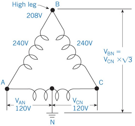
3 phases (L1-L3) where voltage is 240V between any two phases
L1 to N is 120V
L2 to N is 120V
L3 to N is 208V
I found a couple posts where people had delta without a neutral, but I have delta with a center tap neutral and so my reference voltage is between L1 and N. I am struggling to get the total power to be correct for some reason.
I thought I should pick:
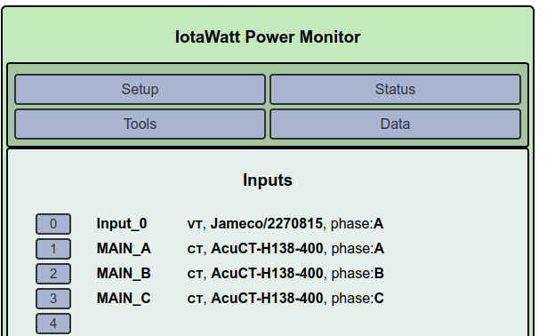
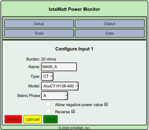
CT on L1 = Mains Phase A
CT on L2 = Mains Phase B (+120)
CT on L3 = Mains Phase C (+240)
But when I do this the sum of the power is incorrect. Is this because my reference voltage is between L1 and N? How can I fix this?
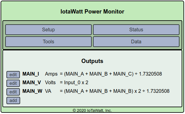
I figured out how to get an output to show a number that matches my meter (see more details below): MAIN_W = (MAIN_A + MAIN_B + MAIN_B) x 2 ÷ 1.7320508
if I set the units to VA I actually get the total watts number that matches my meter and i can plot it
Because my neutral is center tap and my reference voltage Input_0 is ~120V, I definitely need to double the voltage.
Also, my MAIN_I is the 3 phase AC current (total current is lower than the sum of the currents due to current flowing between the phases in opposite directions, or something like that)
MAIN_I = (L1 + L2 + L3) / 1.7320508
This would be adjusting the reference voltage from 208V to 120V.
So when I divide by sqrt(3) I am not converting to 208V, my understanding is this is how you calculate power in a 3 phase system where P = (I1 + I2 + I3) / sqrt(3) * V
see here: Square Root 3 and Three Phase Power - Where Does it Come From - Electrical PE Review
(note I knock off multiplying by the power factor because I pay for reactive power)
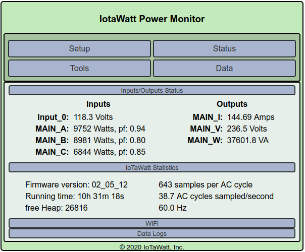
Hmm, now I am wondering if dividing by the sqrt(3) is assuming the system is perfectly balanced, which would not be good. Hopefully with the example numbers in the “Status” screen shot above someone can tell me if I did anything wrong. Remember that MAIN_W says VA but it matches the kW number on my meter (which includes reactive power)
I’ve had a chance to look into this further, and have some suggestions for how to configure the mains. Although I remain skeptical that your meter reads VA rather than Watts, this should make both units measure correctly.
Being unfamiliar with this type of service, I fell back on how commercial meters approach this. I found this to very helpful.
First, you should be sure that all three of the CTs on the mains are oriented the same way. You have designated your Mains to be Main_A, Main_B and Mains_C. Please verify that the AC reference transformer is connected to Main_A to neutral.
It’s not possible for me to know the phase rotation of you B and C mains, but there are only two possibilities and if this doesn’t work quite right, we’ll just try the other.
This is where it’s going to get tricky. Assuming that Mains_A to Mains_C is the split phase and Mains_B is the “high-leg” (208V - neutral), please assign the following phase references:
Mains_A → Phase A
Mains_B → Phase B-C
Mains_C → Phase A and check the “reverse box”
These changes will not correct your history to date. They should cause the correct measurements to be made going forward. So first indications would be to look at the status and see if the real-time Watts are reasonable (post if possible). Also, start a log recording your meter kWh and the date/time of the reading. We will use this as the ultimate validation tool.
I flipped Mains_B and Mains_C so I could set it up to match what you suggested, and the sum of the mains now is very close to the meter, so I think we got it now!
The link I provided above shows a CT on each of the three incoming phases with the ABC references to Neutral, more or less like a star configuration, exept that in your case:
Phase A is the actual phase to neutral so the same.
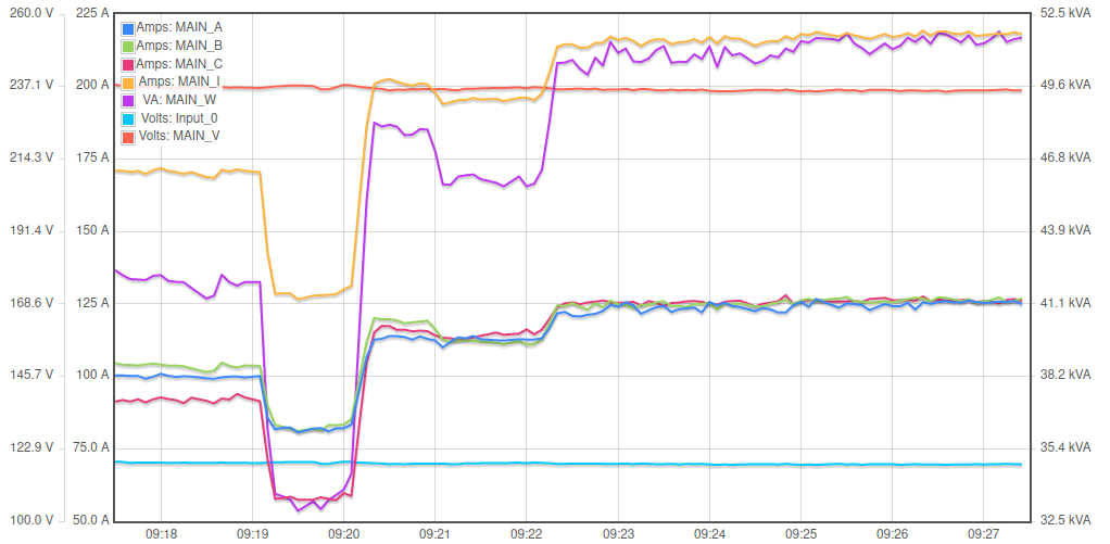
Phase C is actually 180 degrees from A (as in the voltage plot above) so we just “reverse” the CT.
Phase B to neutral, per the plot above, is 90 degrees from A-N and 208V (your old friend sqrt(3)).
In a 120V star configuration, phase B-C is 208V and shifted 90 degrees from A-N. So IoTaWatt derives that reference by numerically shifting the A-N signal 90 degrees and amplifying by sqrt(3). So we can repurpose that derived reference in this high-leg setup as the B-N reference.
There is still a potential issue where we may need to reverse B as it’s 50-50 we have the phase rotation right. Let me know when you have a day or two of meter comparison. If this validates, It will save someone else the trouble in the future.