I am a happy new owner of a v5 and several CT’s.
Now it’s time to deep dive into the installation and it would be great if I could get some help from the community. Just to double check before I proceed with the actual setup.
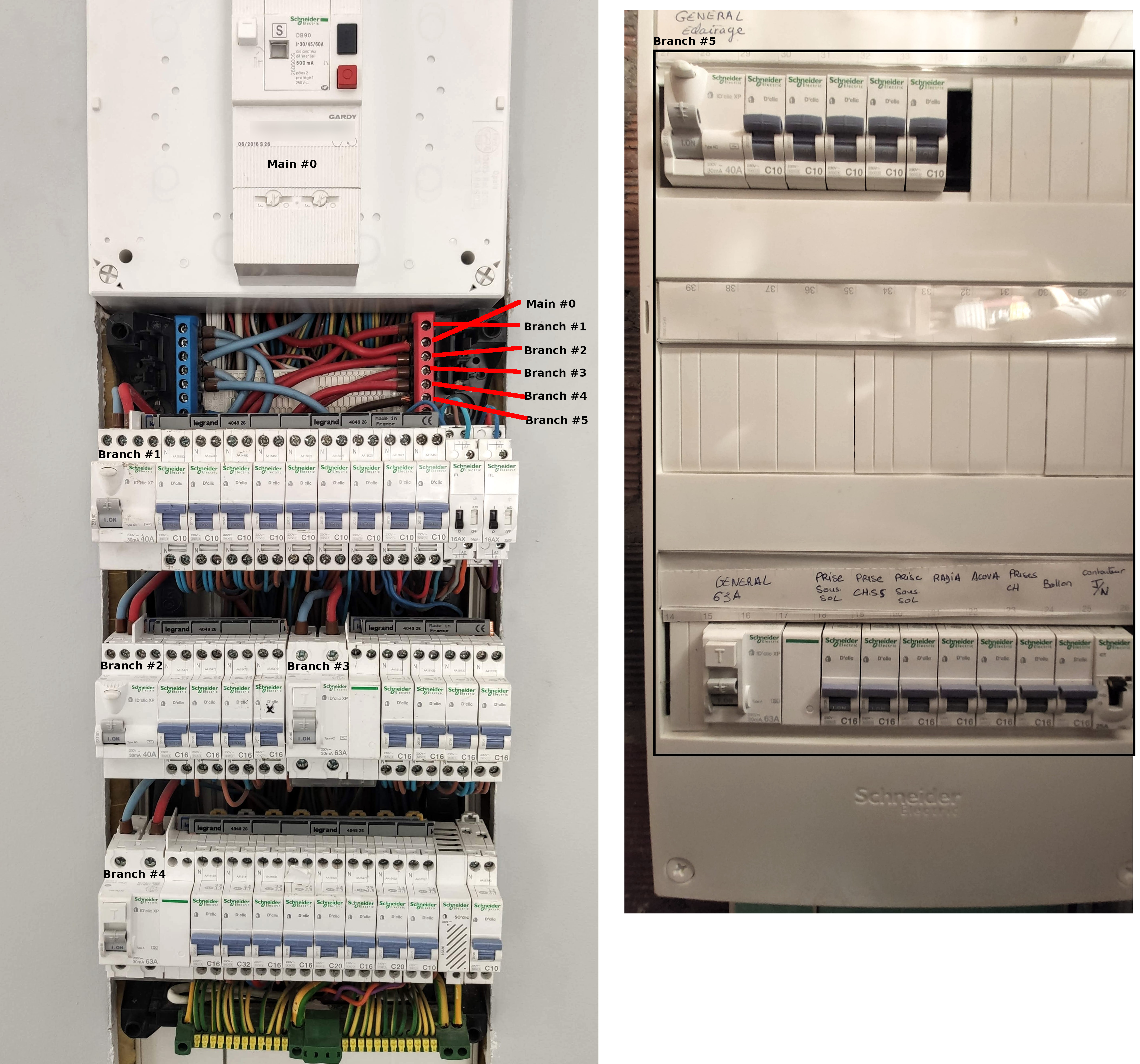
My electric installation is a typical French 230v 50Hz single phase.
I am planning to monitor 6 elements, the main power entrance (1) and the different distribution branches (5).
I will be using the following CT’s for each of the monitored points:
Main power #0: (500mA) -> 400A x 24mm Split-core (ECS24-200-1)
Branch #1 (30mA 40A) -> 100A x 16mm split-core (ECS16-100)
Branch #2 (30mA 40A) -> 100A x 16mm split-core (ECS16-100)
Branch #3 (30mA 63A) -> 100A x 16mm split-core (ECS16-100)
Branch #4 (30mA 63A) -> 100A x 16mm split-core (ECS16-100)
That’s a very busy panel. I’m not very comfortable advising how to go about working in there beyond saying that you might want to consider having an electrician install the CTs. There isn’t much room in there and the 100A CTs need a little space to install.
You should be aware that if I read the main breaker correctly, it has fault protection to 500mA. That can certainly be lethal. So at a minimum, the main breaker should be off and the bussbars tested with a meter before doing anything.
I don’t know what the 30/45/60A rating on the main means, but judging by the size of the Main #0 cable, I doubt it requires a 400A CT (The number on that would be ECS24400). You might investigate it and if the maximum is under 100A, which I think could well be the case, an ECS16100 would do fine. In any case, the ECS24200 should be fine. Your electrician would know the maximum possible.
For the 30A branches, the ECS1050’s would work fine and would be much easier to install than the ECS16100’s that you should use on the 63A branches.
For each branch, you can place the CT on either the “hot” red conductor or the neutral blue conductor. If your electrician pays attention and orients the CTs on the neutral opposite from those on the hot, it will eliminate the need to adjust them in the configuration later.
With this approach, you will have an excess of 100A CTs. You certainly can use them on the 30A branches if you can find a way to fit them. There will be no appreciable loss of accuracy by doing this, it’s just a matter of cost and convenience.
I was not thinking of doing this installation with the main breaker on, I will trigger the main breaker and double check for any voltage with the main distribution platte and each branche.
Better safe than electrocuted
In relation to the tight spacing I was not planning on connecting the CT’s on the distribution plate, but was thinking of attaching them on the cable just on top of each branch breaker.
I don’t know what the 30/45/60A rating on the main means:
This is the typical user facing main breaker (in France) it has a variable Amperage setting, in my case its set to a its maximum 60A
electrician pays attention and orients the CTs on the neutral opposite from those on the hot:
So if I understand correctly I only need to connect one CT per cable pair and it does not make any difference if I connect the CT’s to the Red (Phase) or Blue (Neutral) right?
The important detail is that I oriented correctly each CT from “Source to Load”, so I don’t have to invert this afterwards in the configuration. right?
Or was it detailed I missed…
Another security related question I had was, once the CT’s are connected and the main breaker is activated (Power is flowing) the CT’s should always stay connected to the there load (My iotawatt v5).
Does the iotawatt v5 also have to be powered to not overload the CT’s?
Just want to take extra precautions just in case the iotawatt v5 gets unplugged and I don’t damage my CT’s or produce an incident.
New setup:
Main power #0: (500mA 63A) → 200A x 24mm split-core (ECS24-200) x1
Branch #1 (30mA 40A) → 100A x 16mm split-core (ECS16-100) or 50A x 9mm solid-core (ECOL09)
Branch #2 (30mA 40A) → 100A x 16mm split-core (ECS16-100) or 50A x 9mm solid-core (ECOL09)
Branch #3 (30mA 63A) → 100A x 16mm split-core (ECS16-100)
Branch #4 (30mA 63A) → 100A x 16mm split-core (ECS16-100)
Branch #6 (One cable connected to breaker → 30mA 40A + 30mA 63A) → 100A x 16mm split-core (ECS16-100)
The CTs have diodes to protect them while temporarily unplugged. The IoTaWatt does not need to be powered to afford CT protection.
That configuration looks OK. The CT orientation is only a best-practice. The IoTaWatt will automatically sense and reverse incorrect CTs in a single-phase system.