Hi Bob as per your request I trust this post offers more detail.
IoTaWatt V5 on a Telstra router/modem 2.4ghz wifi with Mac Mojave and Safari browser
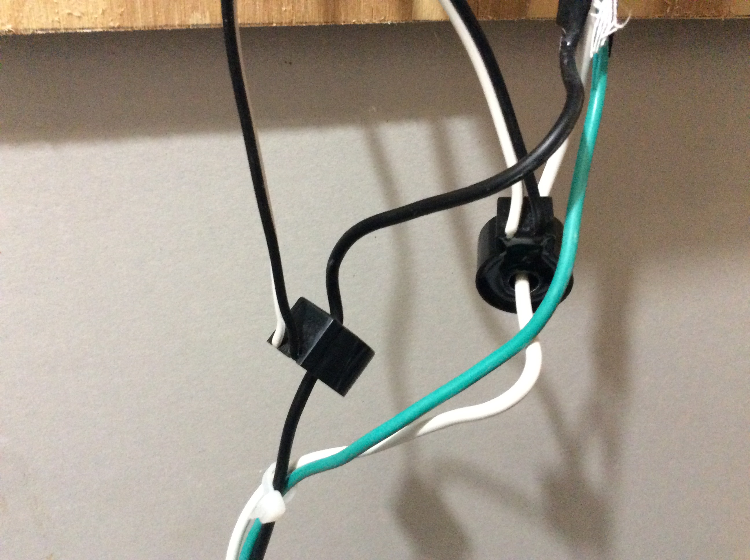
As advised I have had to reconnect the IoTaWatt unit to a new router after initial succesful setup and testing prior to having all the CT’s.
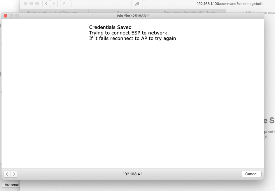
Despite following the doco I get to this screen and am not sure it has completed the connection as I am unable to connect to the IoTaWatt unit. Unit has dull green light glowing.
As suggested I have searched the router for the IoTaWatt host and its not there and does not appear in my wifi list which I assume is correct if connection has been completed succesfully?
See wifi list for no IoTaWatt host name.
Not sure what to check or do next…?
Are you sure this is the WiFi network that you selected? The problem with inability to access would be consistent with the IoTaWatt being on a different WiFi network. You can only access it from the same WiFi network using the zero-config .local method.
Assuming you are confident that you configured this network, the IoTaWatt will renter WiFi configuration mode on power on for three minutes if it does not connect to the configured network. So to test this out, you can move the IoTaWatt well outside the range of local WiFi networks and power up. It should enter WiFi config mode (RGG). You can then login to the AP and configure your network again. The scan will not detect it, so you will need to input the SSID and password. After you do that, power it down and move it back intop range of the WiFi network. Upon power up, it should connect.
One other indication that it is now successfully connected to some network is the fact that the LED is not dull red. When a new IoTaWatt is first connected, it must get the time from the internet. Until it does that, the LED is dull red, turning to green once the time is acquired.
Another avenue of persuit here is to remove the SD card and post the file /IOTAWATT/IOTAMSGS.TXT. That message log will contain the name of the wifi network that is connecting and the IP address assigned each time.
Please try one of these out and post your results.
Iotawatt is supposed to be here tomorrow…is there anything I need to do as far as apps or internet that I can get ready before it comes…
What do I need to do to be able to view homes usage-graphs? I have an iPad as the viewing screen. Is this explained somewhere on here for ppl like me who barely know how to even get an app at all lol
Thx overeasy, that put a lot of my confusion at ease…
What do the graphs look like that are available without an additional web server?
Also does anyone know which web server I need to use these graphs…
That looks like a graph produced by the local IoTaWatt graph utility. You could also get a similar graph using an Emoncms server.
ok I probably did some stuff wrong…
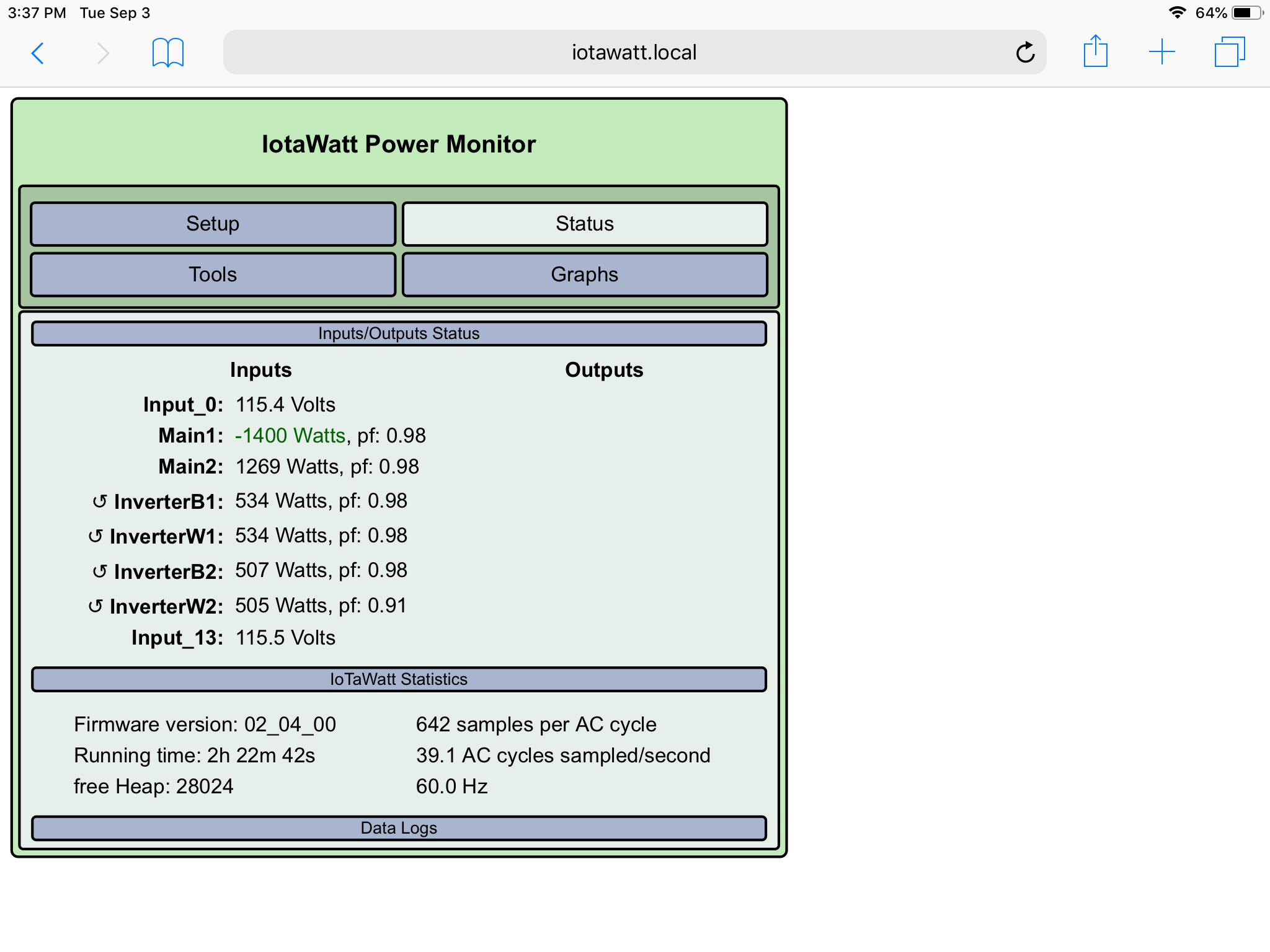
It’s showing negative on mains and reversed cts on the 4 wires of the 2 inverters. I’ve got one ct on main going one way and the other the other way. I think everything’s ok except the mains showing negative but if I flip the ct on mains1 then both cts with be pointing the same direction
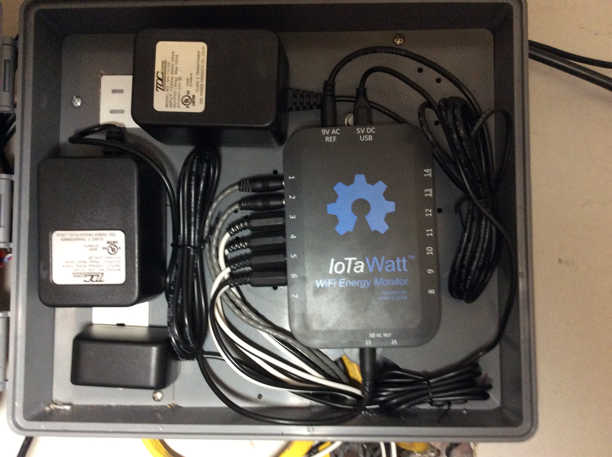
Can you post the input Setup display please and describe what you think is going on in your setup?
In a single VT split-phase system, the CTs are installed in opposing orientations because one of them is using the other leg for a voltage reference, which is 180° out-of-phase. In your case, I think you are using a discrete VT for each leg, so the CTs can both be oriented the same.
The CTs on the inverters are all showing reverse power but the IoTaWatt is “correcting” it to be positive. In this case, you probably have the CTs all oriented the same way.
There are a number of ways to adjust these conditions. The one I would recommend would be to reverse the two VTs in their sockets, and then reverse Main2 either physically or by checking the “reverse” button in the input configuration.
Couple of other things I noticed:
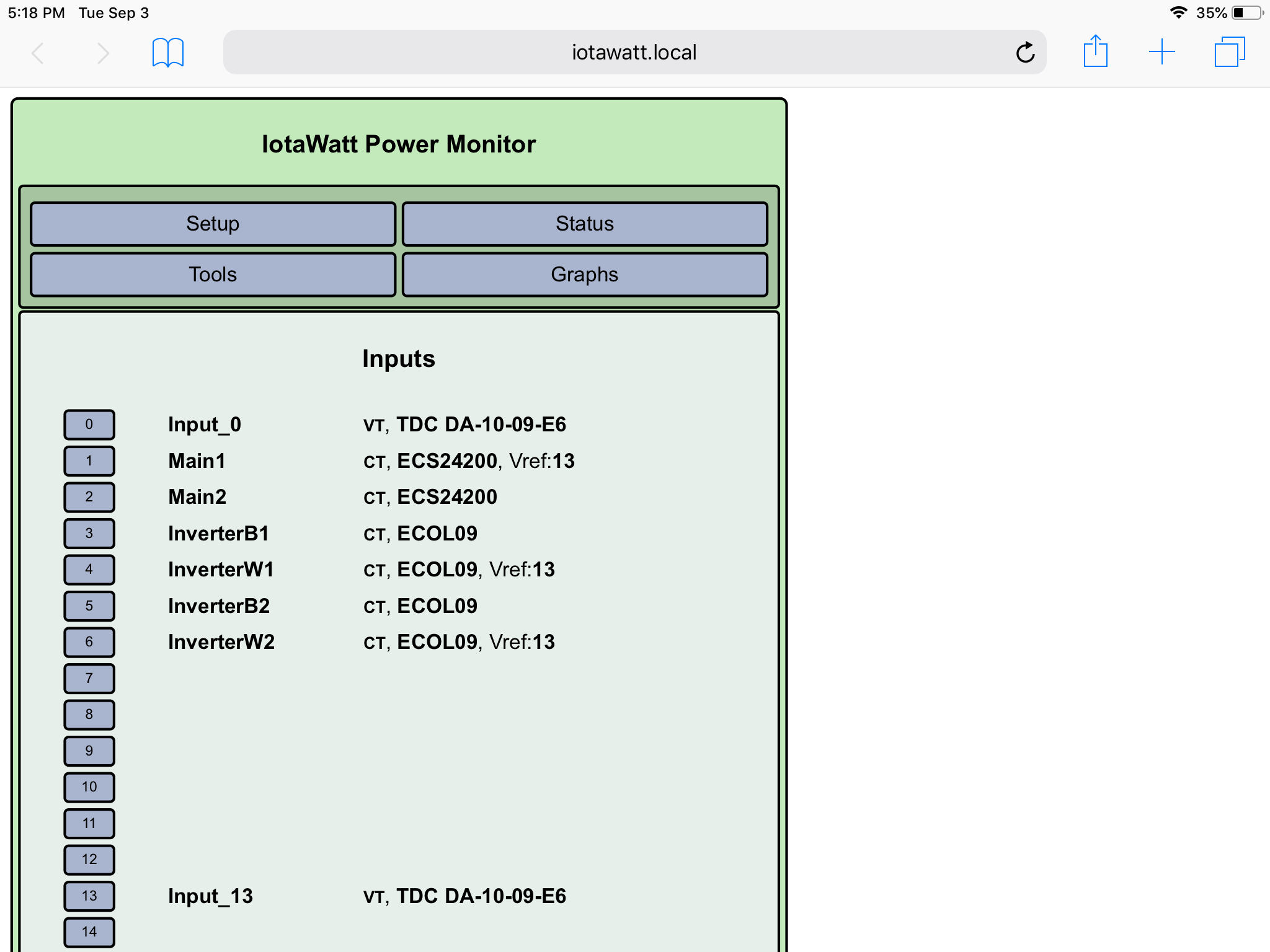
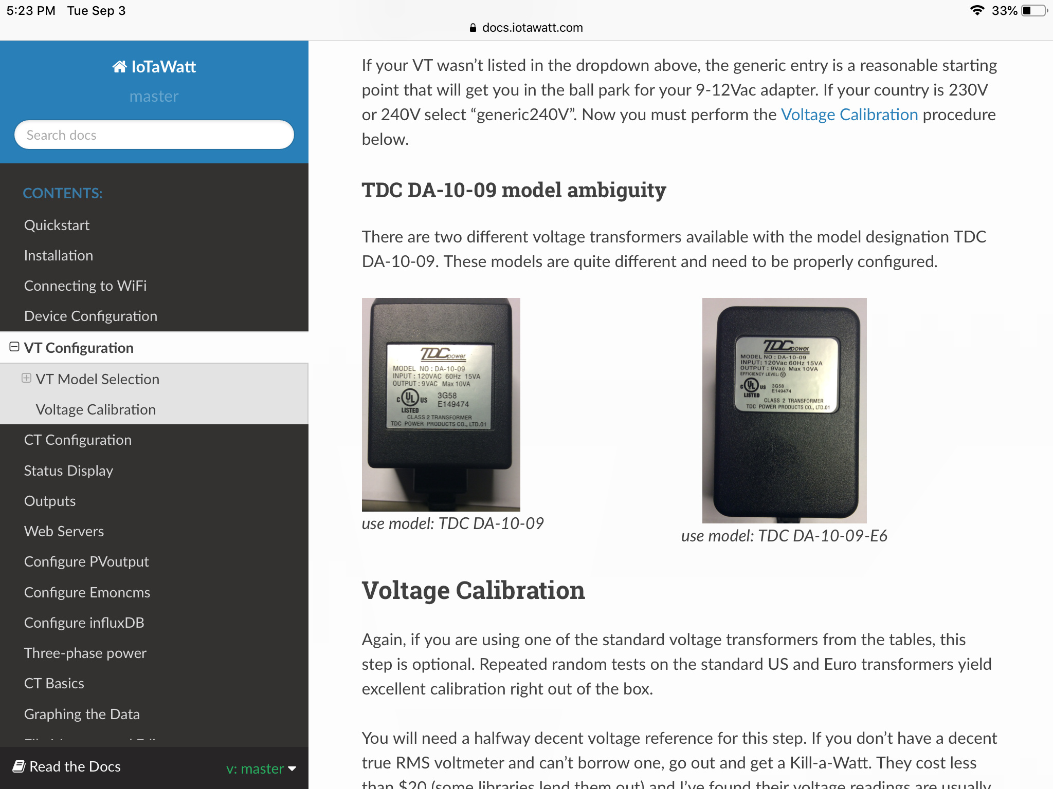
Your voltage is 115/230 which is not typical but possible. Have you entered the correct model for the VTs? They should be TDC DA-10-09-E6.
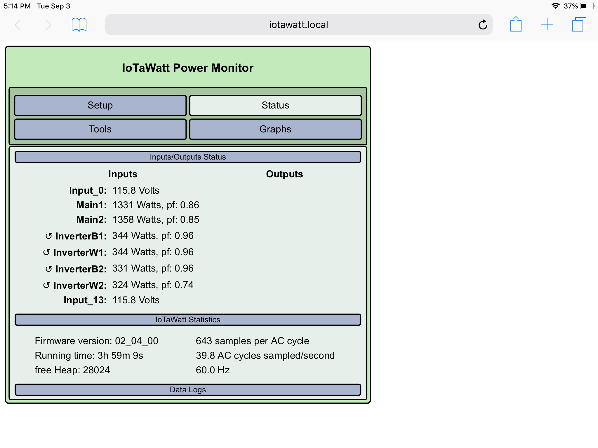
I noticed that the power for InverterW2 is a couple watts lower than it’s counterpart, but more importantly, the power factor is quite a bit lower and not typical for an inverter. You may want to check that the mating surfaces of the CT are clean and that the CT is securely clipped together.
I reversed the ct on main1 (before I read that u said to flip ct on main2) but I’m not getting a negative reading anymore.
I think I’m using the Vts on the right in the pic, that is the one I chose in the setup.
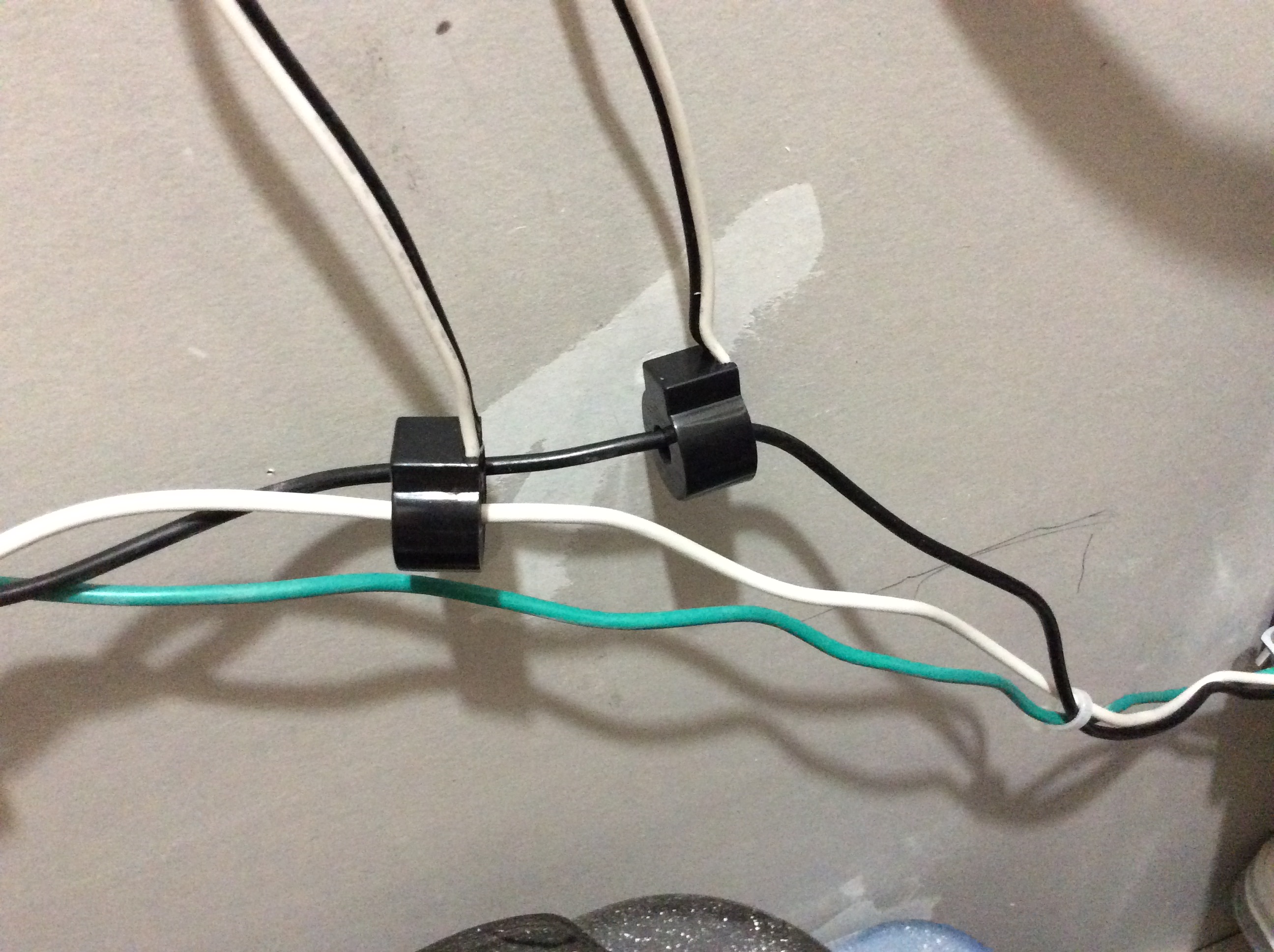
The cts on the inverters say on them to have this side facing the source which I’d assume would be facing the inverter, this is how I installed all 4 of them…so this is wrong? Are u saying to switch the headphone connections as in making input 3 actually input 4 etc?
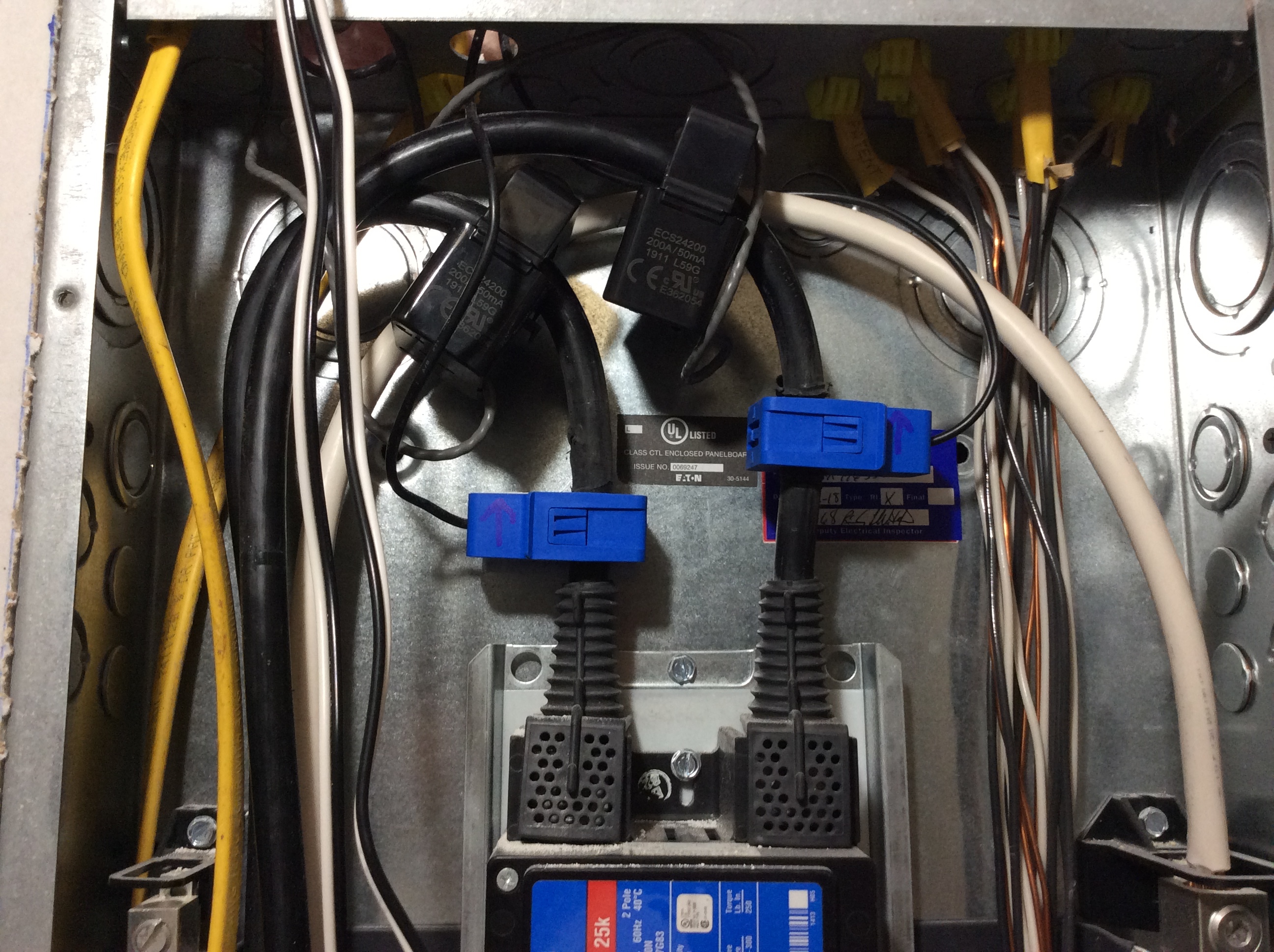
pf on w2 has a solid core ct and it it plugged into its jack correctly and it’s clean
The VT configuration is correct.
The only thing I don’t like now is the difference between InverterB2 and InverterW2. Those conductors have exactly the same current, so there is something going on. Also the .74 pf indicates a problem. In the last post I didn’t realize that you have solid core CTs. Those are very accurate, so wondering what’s going on. Maybe some pictures of the install? You also have more of those, so swapping in another there might be a useful diagnostic.
I notice that the voltage on the two legs is the same. Will be interesting to plot the two together for a day. I expect they will correlate very well and show only a few spikes from high wattage 120 appliances like hair dryer or toaster.
I will do more testing tomorrow when there’s sun for solar readings…I appreciate any advice…
Yes sir I can’t wait to get a graph going. I turned on the microwave to see what happened to volts during unbalanced legs and the voltage dropped 1.2v (says iotawatt) on the leg the micro was on.
I guess it’s not showing a pf for solar in the pic due to not much power going thru the wires… Tomorrow I will switch the cts (for inverter2) at the jacks to see if the low pf follows the ct… if it does then I’ll switch the ct with one of the 3 I havnt installed yet
Sounds like a good plan. My money is on the problem following the CT.
When the microwave drew down the voltage on one leg, you should have seen an almost equal increase in the other.
Where do the SCT013 CTs on the mains go?
The blue cts? They go to the inverters. They are limiting the power the inverters produce to not feed the grid.
Just changed the direction of both main cts fyi…I realized I was using the wrong voltage reference for each main so that is now correct. Which in turn corrected the reverse symbols on the other 4 solar cts.