So im in the process of installing the ct’s following along with the manual, and have a couple of questions:
Am i right in thinking that if i dont tick “use derived” its then using “direct reference”??
As i dont have additional VT’s, i will need to use “derived method” therefore i need to identify what phase each and every input is on?
In the docs, it mentions that the arrow on the ct face towards the load, do for incoming mains it would pint from street to breaker??
But then the docs say for the echun clamps, its the other way round? Is this stil the case? Im using ECS16100 and ECS1050
Thanks
Correct (But they are not mutually exclusive)
Correct
It’s more important that they all point the same way. Many VTs are not polarized so which way is kind of arbitrary. The setup procedure addresses that and when to “reverse” the VT if it’s backwards.
Again, more important to all be the same way.
1 Like
Thanks @overeasy for confiming
Ill ensure all clamps face the load, that way i know they match.
Now just need to work out what is on what phase…
Thanks again
While i wait for my spaky to show and run a new cable, id thought id setup my influxdb2 instance
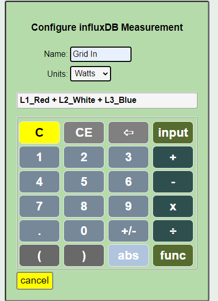
Can you combine inputs in the measurment field like so?
I cant seem to save the config
EDIT: Nevermind - It doesnt like the space in the name!!
1 Like
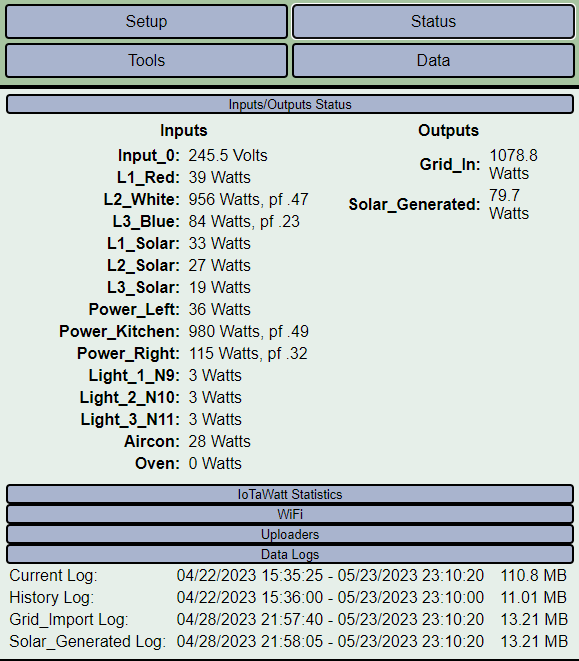
So i finally have eveything setup and installed.
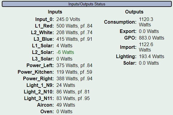
Looking at data, something seems off with the solar…Seems very high for my mind, considering its 11pm at night and not generating anything!!
Can CT’s pick up interferance from other cables…if it too close to incoming mains maybe??
Same for aircon perhaps??
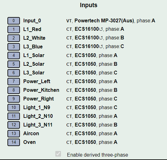
Input page
any advice??
Ill be re-checking my CT placements tomorrow
EDIT: Input_0 VT is actually connected to Phase C if it matter!!
Cheers
Yea, it does. That’s like step one of derived install. Your setup is clearly wrong.
https://docs.iotawatt.com/en/master/threePhase.html#configuring-derived-reference
So maybe I i have misinterpreted the docs. I assumed it was showing how to identify each physical phase which I already knew. IE phase a=red, etc etc as I can tell from behind the panel. But in actual fact that is wrong in iotawatt terms as the vt is always on A regardless of panel.
What would be better, is if I connected my gpo to phase A in the panel?
You’re getting hung up on the similarity of naming conventions. In retrospect I probably should have named the derived phases X, Y and Z to avoid this. But that ship has sailed.
Three-phase phases are all relative. So, with IoTaWatt we arbitrarily call the phase with the VT phase A, then determine which is 120 degrees behind and which is 240 degree behind.
you
There is no need to move your GPO. Just call L3_Blue phase A, verify with a load as in the docs, then move the load to another phase as instructed to another phase and identify it as B or C as described in the docs.
Thanks
Ive changed my what i had as Blue (C) - to say its Phase A - Now i need to test each other phase - I know what branch circuits are on what (physical) phase, just dont know the values in Iotawatt
So, i understand. What ever brach circuits i had as C, i change these to A - and so on for the other 2??
Alos, when i watch the status page, i notice the 2 lighting circuits say reversed. All my CT’s face the same way and randomly Light 2 reverse symbol will come and go
EDIT: Just watching the status page, random inputs will show the reverse symbol briefly then dissapear
Have you followed the instructions in the docs that I referenced for configuring derived three-phase?
I have for the mains. My 3 main inputs were matching values with that of my meter, well very close too, as it jumps around
Where i had red as A its now B, white B now C, Blue C now A
They should be within 1% of the meter. You cannot do that looking at Watts, you need to compare kWh over a period of time when you have used 100 kWh or more.
If your phases are color coded after the mains, it should be easy to assign the correct phase. Otherwise you will need to follow the wires, or an alternate method is to use a voltmeter to measure the voltage between the mains and the branch. When you are comparing to the correct main, the voltage should be zero. When you compare to the other two, the voltage should be around 400.
With the branch, i already know which physical phase each branch circuit is connected to…
Do i use the physical phase in setup? or whatever branches are physically connected to A, do i select B as that what the Mains is??
Assuming your mains are correct, and I’m not convinced they are, you would assign the same phase as the main it draws from. I don’t know any other way to explain it.
Ive gone through all the setup procedure and believe have it right.
My solar figures all but macth that of my inverter for a daily consumption.
Obviously it wont match exactly, but how close should it be? within what?
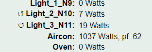
Also, ive noticed my oven figure jumps around when its off - can ct’s get interferance from other cables or ct’s??
Once i work out how to read my utlity meter and can track a 24hr period to confim setup
Yes, that can happen, but it is showing zero in this snapshot. Better to plot it over a span of time and look at the plot as well as the statistics tab in Graph+ to see the nature and extent of the “jumping around” which is not very descriptive or helpful.