I’m interested in getting an IoTaWatt, it looks like the best “no cloud” solution out there.
First question, I keep all my IoT and home automation stuff on an isolated VLAN that can only talk to my HomeAssistant server, and basic network resources (pfSense router running DHCP, NTP, limited inbound-only-access from my PC to configure devices).
Are there any issues I would expect with an isolated configuration like this?
Second question, I have a LOT of circuits in our panel (its completely full)…single-phase 200A main, 1x 240V generator interlock circuit, 7x 30-60A 240V appliance circuits, 5x 120V “single breaker” circuits, 18x 120V “half breaker” circuits. I know I want to be able to track some things (e.g. both furnaces to know when aux. heat is on, washer, dryer, sump pump) to drive automation in HomeAssistant, but are there suggestions how to decide what I should/shouldn’t pick and what circuits to ignore? Can I loop a CT over say 3-4 adjacent 120V breakers and get an accurate combined reading?
I do know what is on every breaker (about 3 pages of bizarre mismatched mix of rooms) but I have a hard time deciding if I actually should bother with many of them - e.g. “all the bathroom outlets”…or one breaker is “just the kitchen lights” another “just the smoke alarms”.
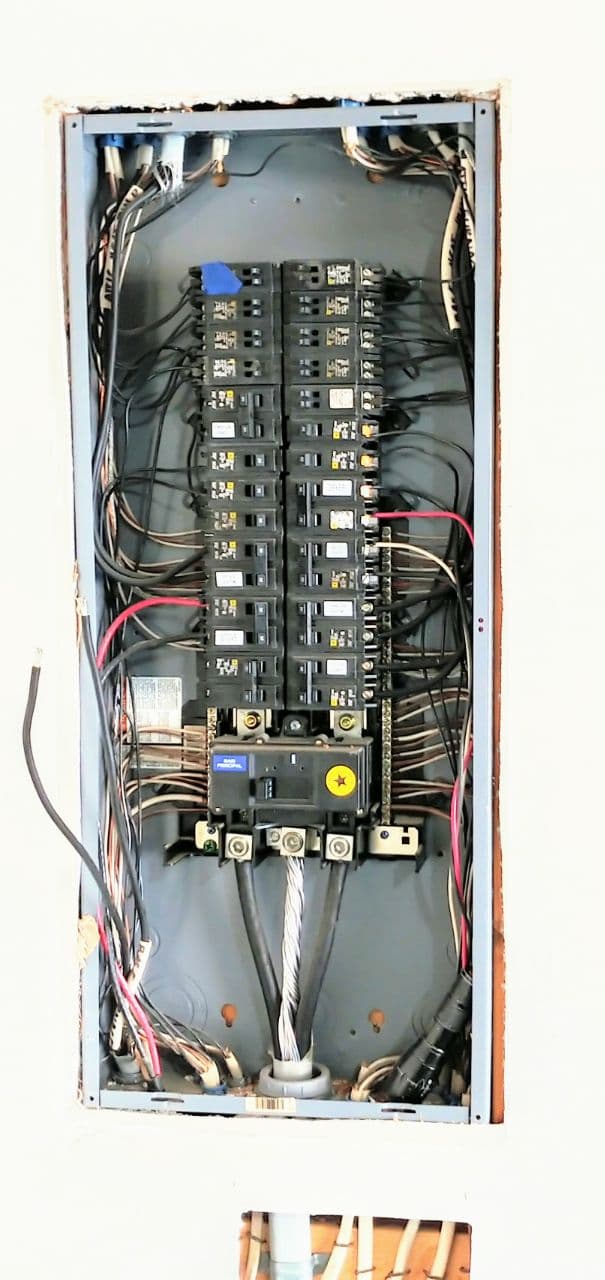
I’m attempting to attach a picture of the breaker box I snapped when the electrician was wiring up the generator…to get an idea of available space and wire density (bearing in mind 2 of the biggest circuits are not connected to their breakers yet in the picture…they are now).
I also have concerns that there isn’t enough room for 1 CT per circuit (especially on the half-breakers) and I worry with so many wires it may be difficult to get the wires out of the box to the control brain(s)…especially if I end up waiting for the model that has more inputs or get more than one? What’s the usual way to get all the wires out - how many will fit thru the couple remaining 3/4" knock-outs in the bottom of the panel box that are unused?
I understand one of the power bricks us used to tell “voltage”. How does this work with imbalance between the half-phases? I see sometimes ~1V or so difference between the L1/L2 to neutral, will that affect the readings?
Finally gather it also requires 2 power bricks, one for power one for voltage sensing. Is there any way to reduce this down? My panel box is in my garage, and there is exactly 1 duplex outlet for the entire 2-car garage. Its also a GFCI so I can’t put a multi-tap cover on it because the screw hole is in the wrong place and covers buttons…and with the box full its going to be very hard to add more outlets by the box. I don’t suppose there is some way to use a single wall-wart for both power and voltage sensing? Or could I make a “Y” cable that can rectify and step down the “sensing” voltage to power the board off the one wall-wart?
 .
.