Hi
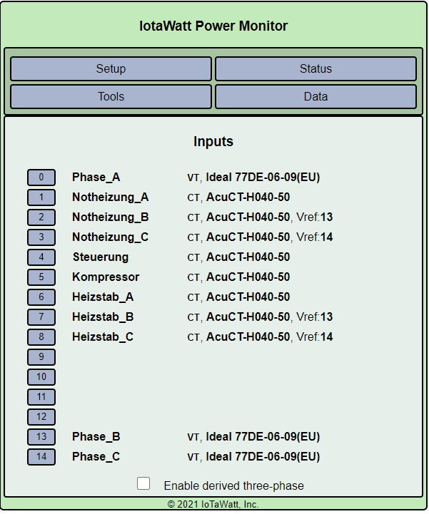
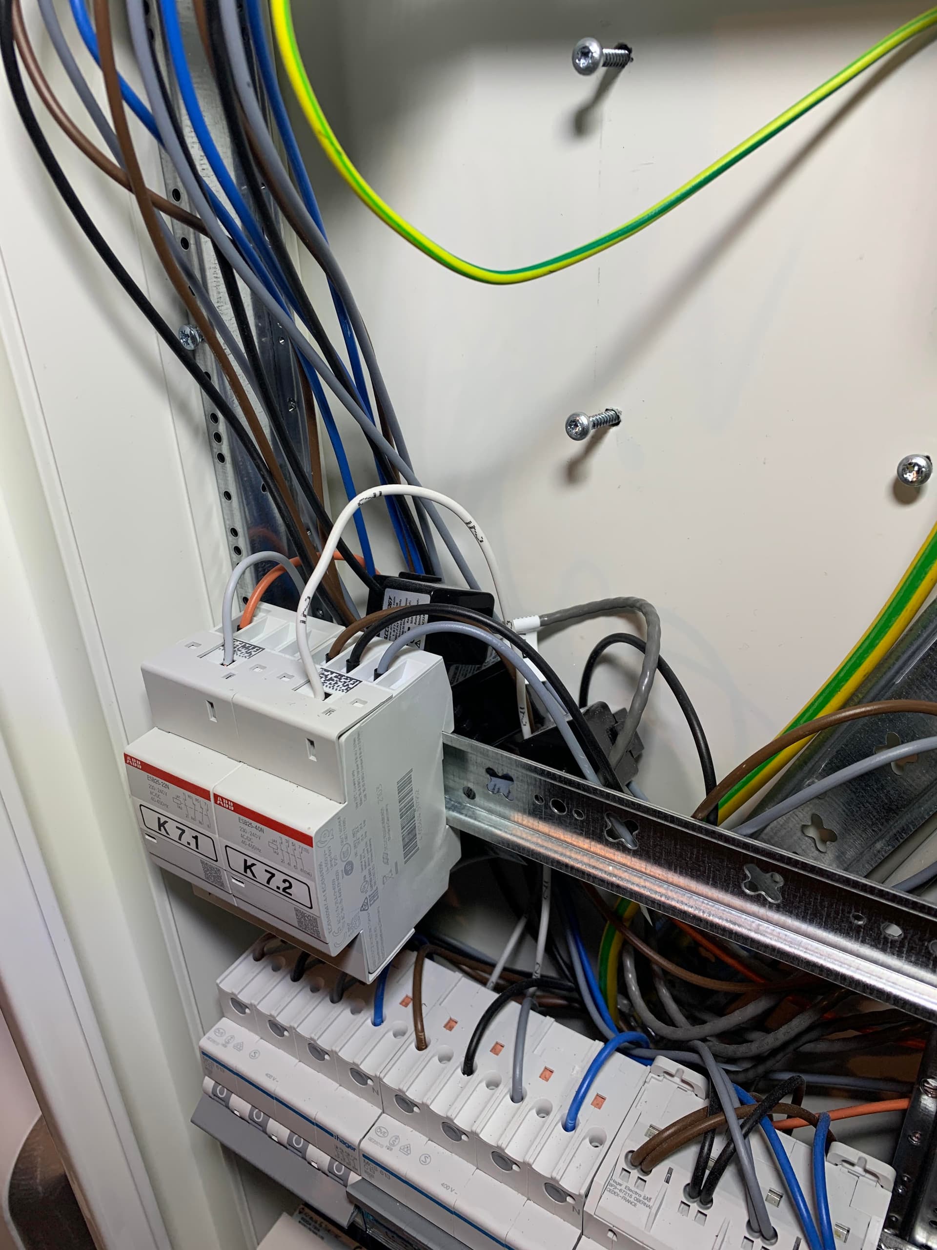
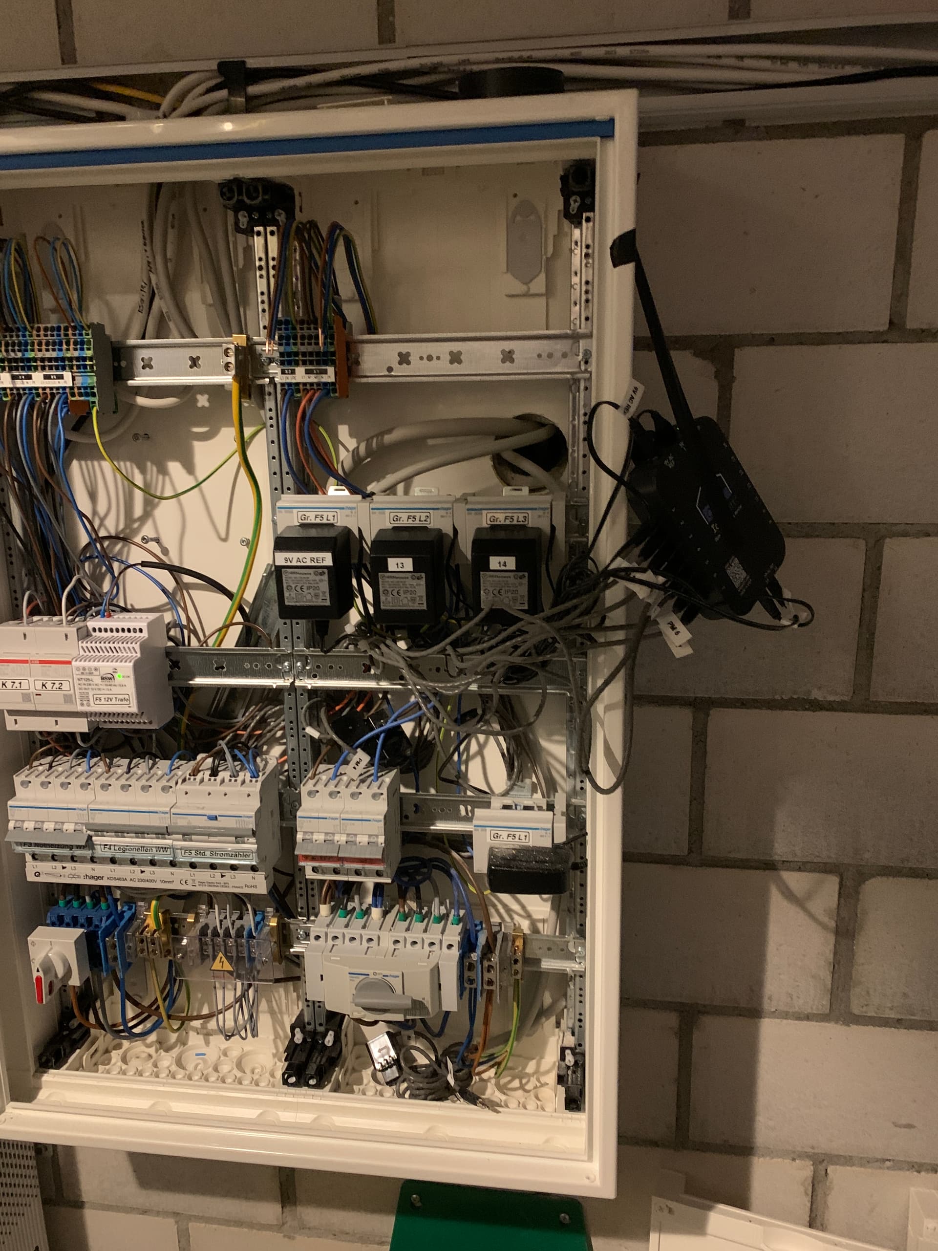
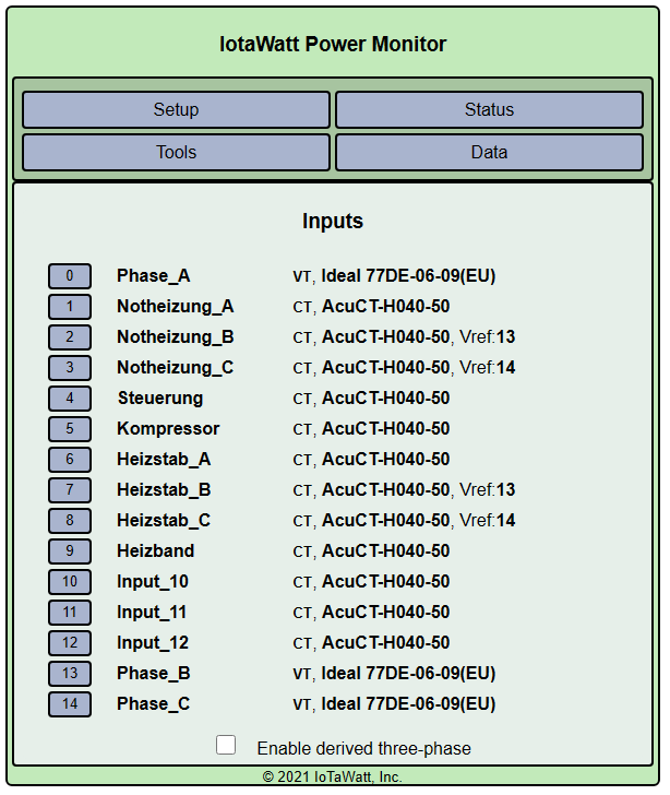
I have my IoTaWatt installed this week. It is a 3 phase system in Europe and I use 3 VTs the 3 phases are called Phase_A, Phase_B and Phase_C. At the moment only the 3-phase 4.5kW resistive heater (Heizstab) is connected, all the other circuits are not powered but all the CT are installed. All CT face the same direction.
My observation is:
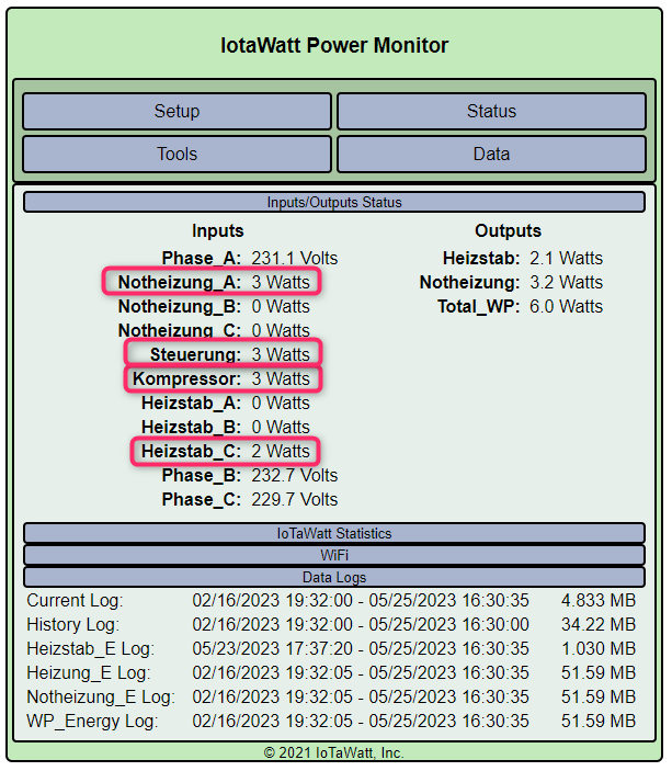
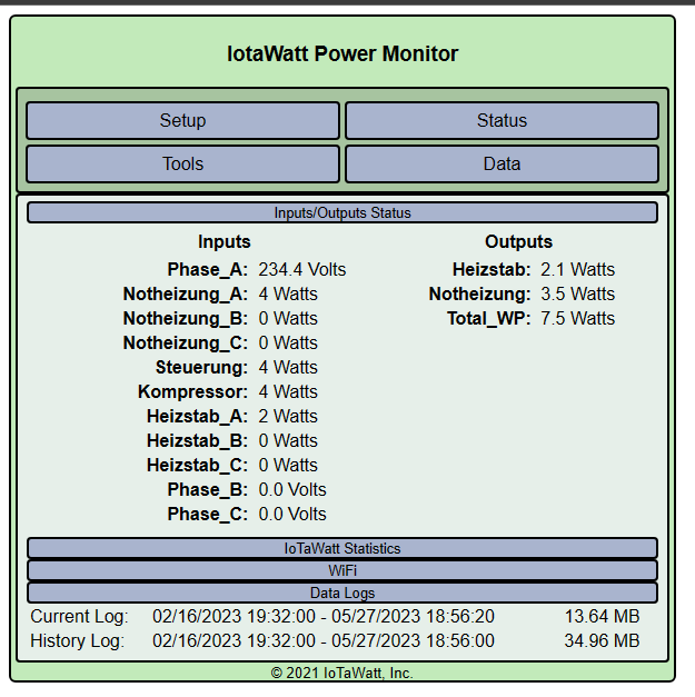
I get small spurious power readings an all other channels even tough they have nothing to do with the Heizstab and are not under power. The Wh count up…
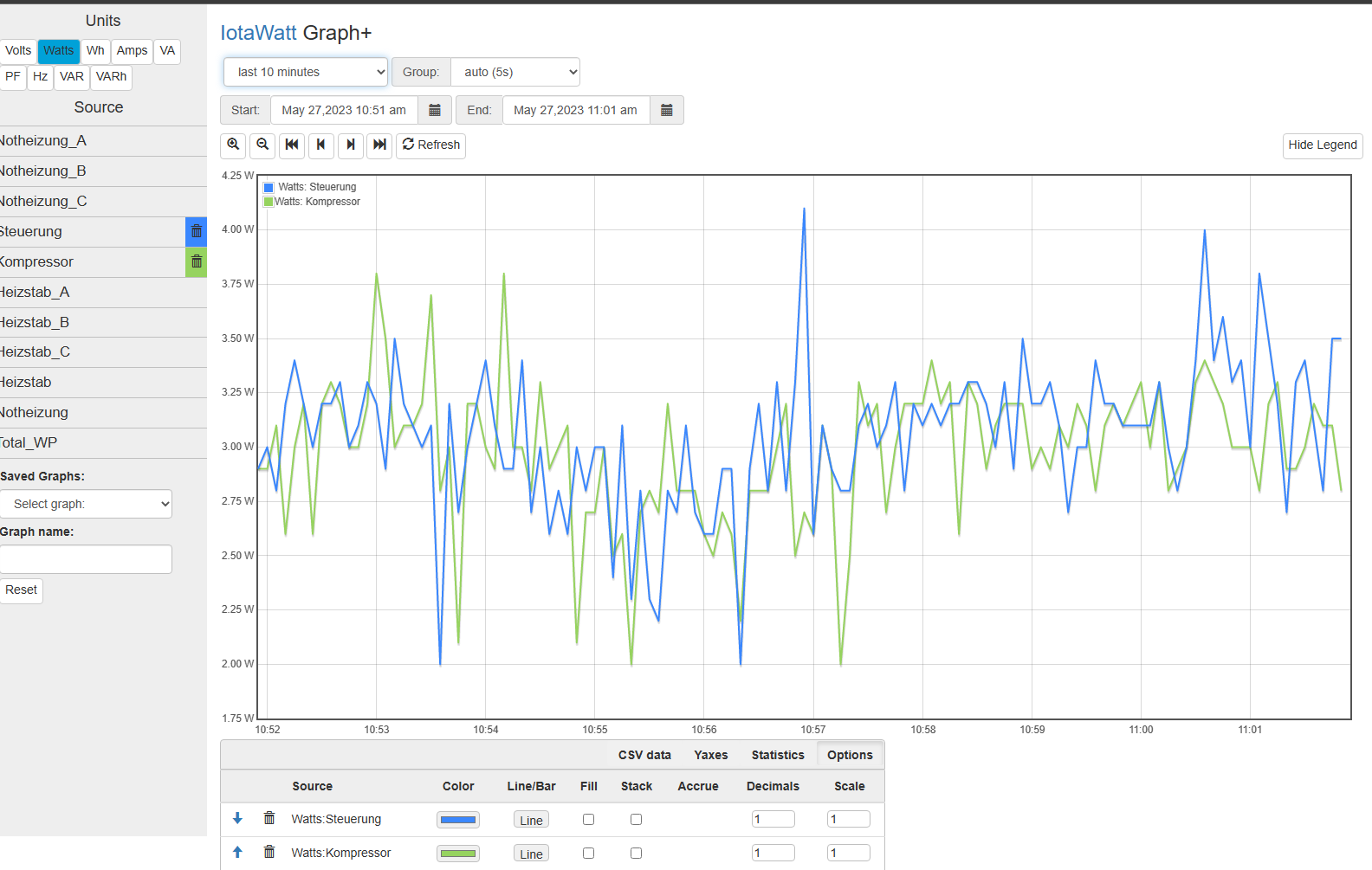
As you can see in the screenshot there are small power readings even though everything is off at the moment and e.g. nothing is connected to Steuerung or Kompressor, so no standby current or similar possible.
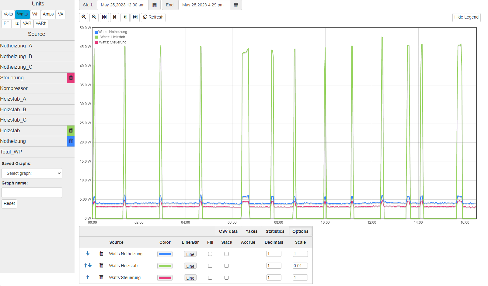
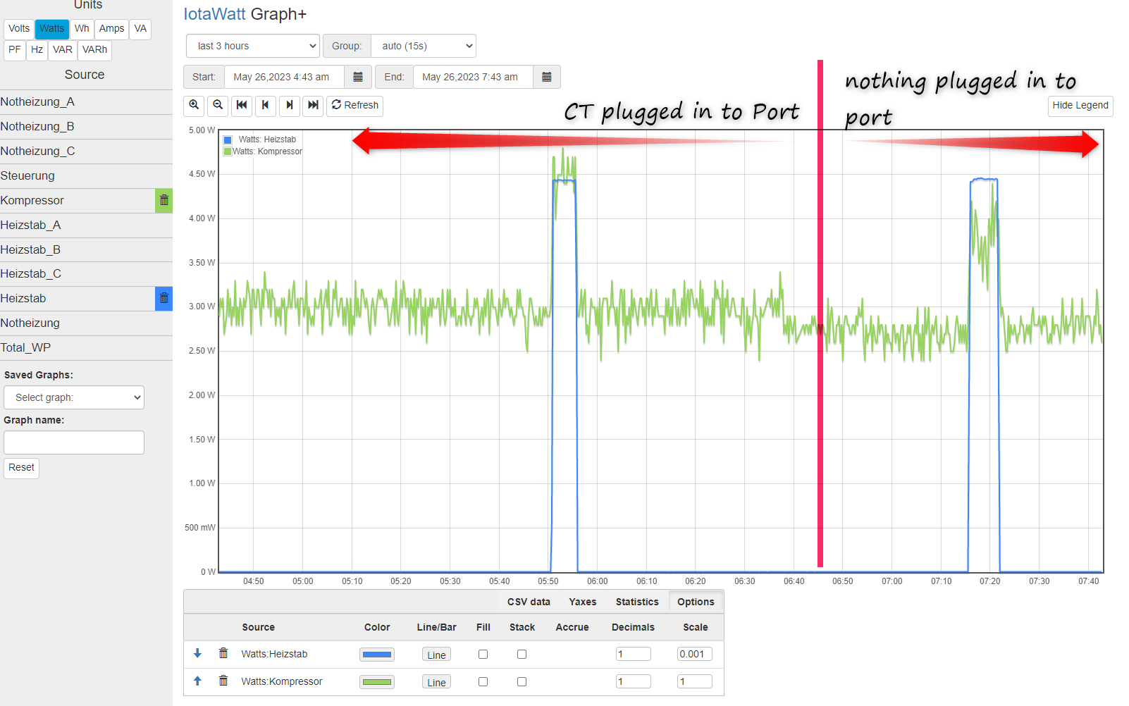
I found in the data that as soon as the Heizstab turns on the power readings of all the other channels go up as well. It looks like some kind of interference from on channel to the other or from one CT to the other.
Shows the change in power for other channels as soon as Heizstab turns on. The Heizstab has a power of 4.5kW (scaled by 0.01 in the graph to show the effect)
I unpluged CT on Port 5 (Kompressor) and the readings are the same, no difference, fluctuating between 0W and 3W and as soon as the Heizstab turns on it increases.
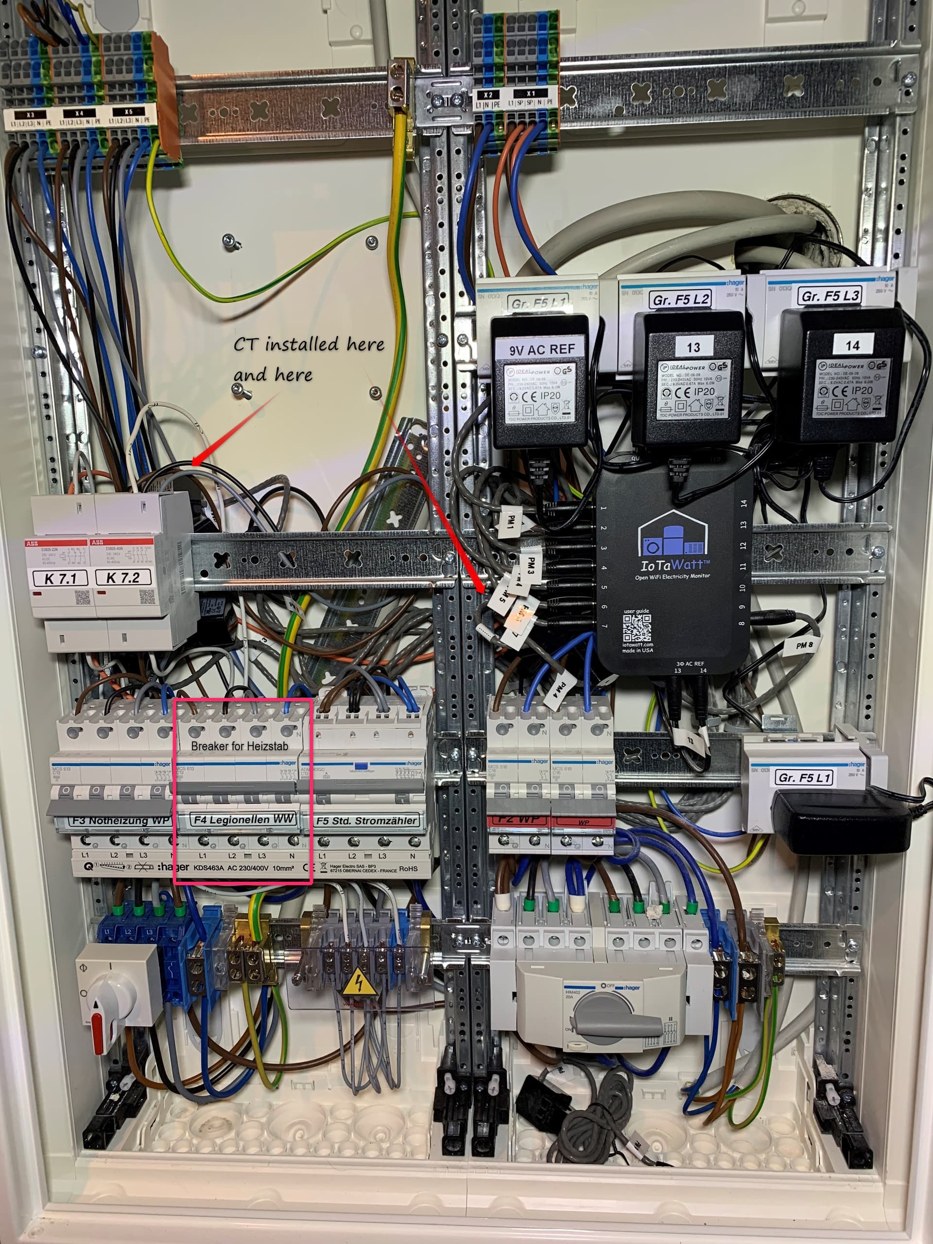
I am suspecting the placement of the IoTaWatt on the din rail right on top of line-voltage cables causing this. Understand that at 230V, 3W of power is a very small amount to measure and any noise can easily cause this.
If possible, can you try moving the IoTaWatt away from the din rail as much as possible to see if it improves? If so, moving up to the rail above as far from the cables as possible may be the solution.
This is a unique problem. In the few cases of crosstalk that have come up, the usual issue is the CT wires or the CTs themselves are picking up induced signal from a nearby hot wire or, in the case of a CT, another very close CT. Not the case here as you are disconnecting the CTs.
Another source, in only a couple of cases, has ben a defective TVS diode or ADC, but your problem is across multiple TVS diodes and both ADCs.
So now it is a unique new problem, and I’m looking at what is relatively unique in your installation. Two things stick out:
You are using five integrators. While I don’t see how they can affect the inputs, I question the need for them and highly recommend that you try to eliminate any unneeded.
The overwhelming majority of IoTaWatt three-phase users, and there are a lot of them, use derived reference. I don’t have a three-phase installation to test direct reference and can’t say for sure that this isn’t related to the three VTs. I do use multiple VTs in my home monitor, but they are measuring 120V and 240V in phase with one another. It could be something there. You have the problem on both Steuerung and Kompressor that are both on Phase_A on input 0. Could you try unplugging the Phase_B and Phase_C VTs and see if those two return to zero?
I can see that you went through a lot to use direct reference, but I can tell you that looking at how close your voltages appear to be, there would be no practical difference using derived reference. So if removing the two VTs resolved the problem, that would be my recommendation.
The status screen after unlugging the VT B + C. There is no current running through the panel at the moment everything is off except for the IoTaWatt. The IoTaWatt power supply is not going through a CT clamp.
The power readings of phase B + C CT inputs are now constantly zero (as would be with no voltage reference). All phase A CT inputs display spurious readings.
Next test:
Now I unpluged all the CT and VT B + C just VT phase A is plugged in and the readings are the same spurious power readings on all phase A inputs even though no current flow in the panel and no CT connected to IoTaWatt. Somehow I think there is something wrong with the unit? What is your interpretation of this behaviour?
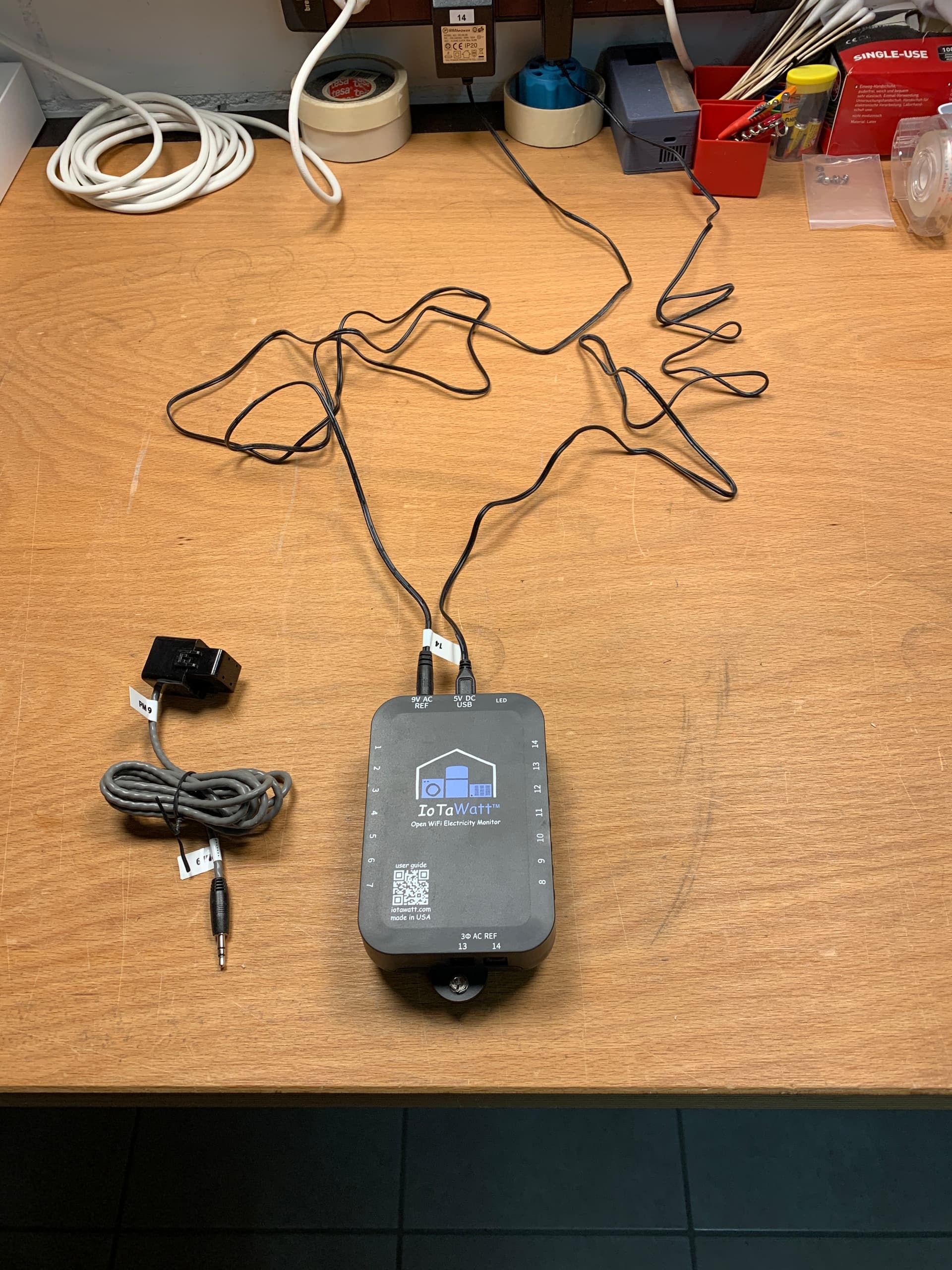
To determine if it really is a bad Iotawatt or just your installation, I would move the Iotawatt several meters away from the panel. Use an extension cord for the AC ref and USB power supply.
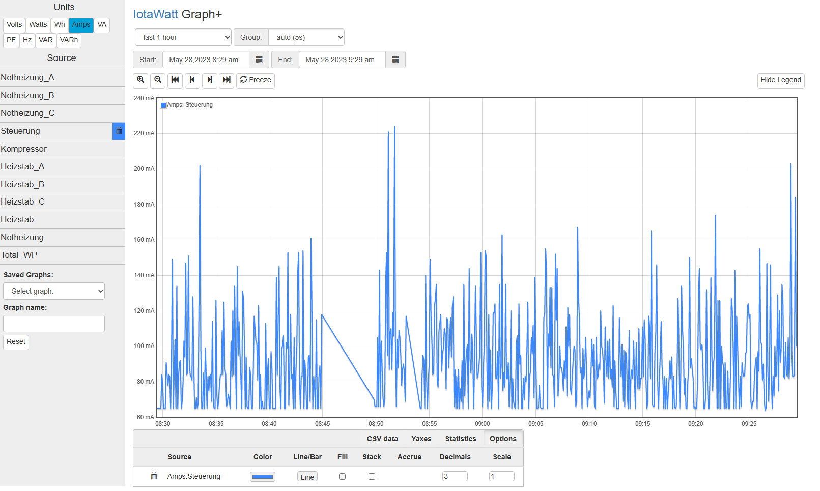
Graph the amps and the PF from one or more channels.
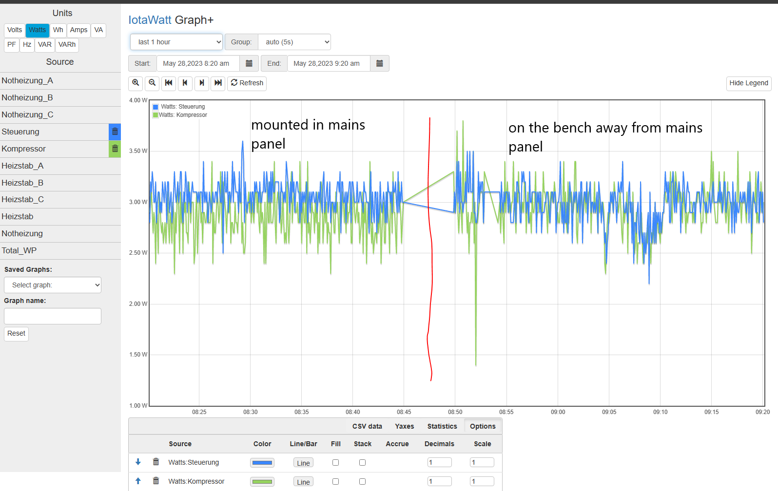
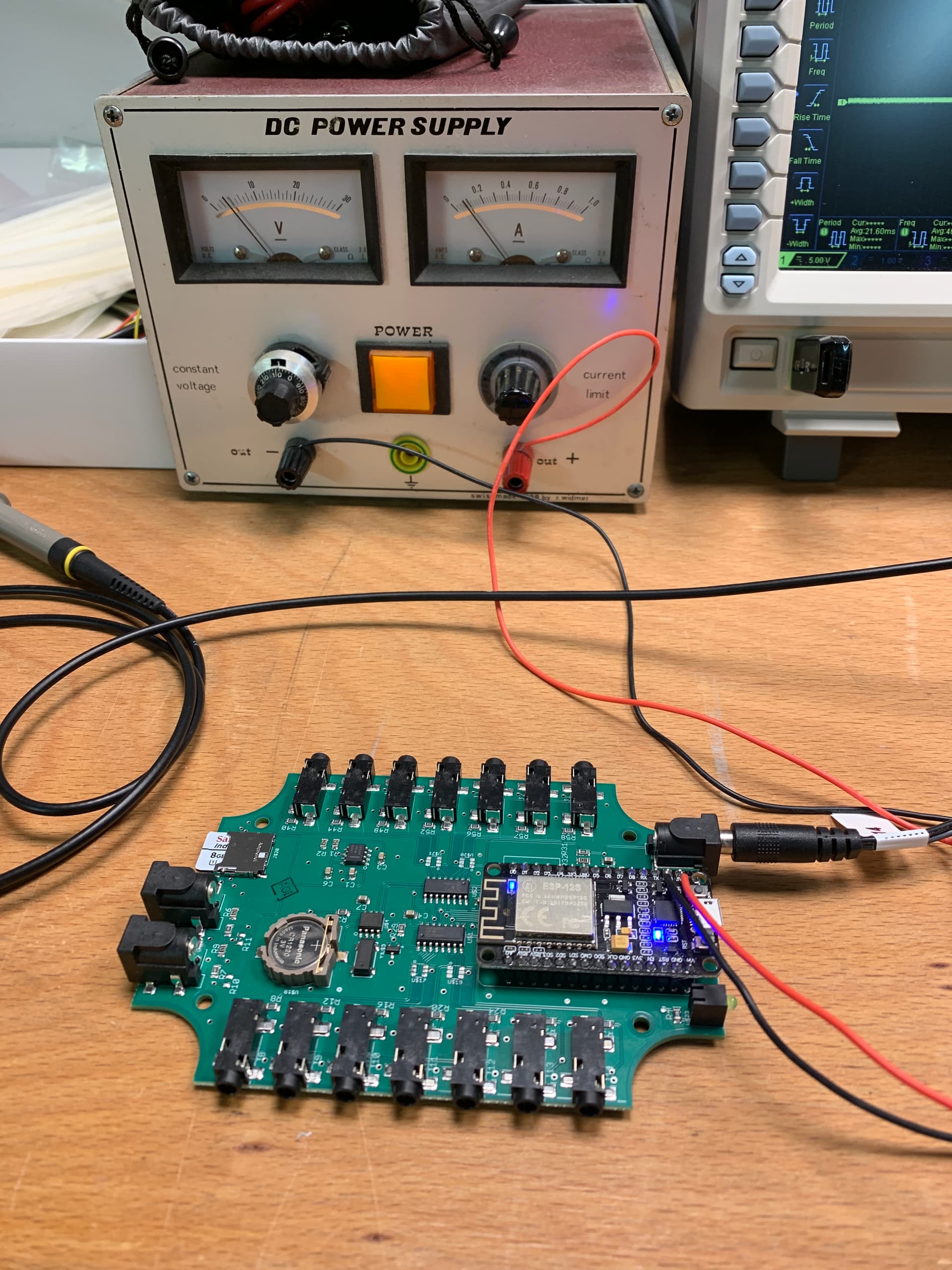
on the bench, just power supply and one VT connected.
Unfortunately the readings are still the same, there is no difference in readings between being mounted in the mains panel (as shown in earlier posts) and on the bench.
That seems to indicate your device has an issue. No idea what it might be. I doubt that a factory reset will fix it.
Even when I set my unused channel to think it has a 600A CT, it doesn’t show as much phantom power. Yours is set to a 50A CT, so it definitely is showing much more noise than mine do.
I have some ideas to pursue this, but right now it’s a big holiday weekend here and it will need to wait until Tuesday at the earliest.
In the meantime, let’s put this in perspective. Show me a meter that claims better than 1% accuracy, or even 0.1%. An input with a 50A CT at 230V has a full scale of 11.5kW. 3W is about 0.03% of scale. My point is that you are probably getting good data on usage notwithstanding this phantom reading. Initially you had to scale the comparison by 0.01 to observe the effect.
I do want to understand this, and what you have done so far is helpful to eliminate many potential external causes. Next I’ll be turning to looking at internal issues to the extent that you will perform the experiments.
I have a unit here that Chas experienced a similar problem. I’ll be putting the oscilloscope to that as well.
In IMHO the issue is not related to accuracy but to the signal to noise ratio which is too low for my unit. I have several Shelly in my house and their accuracy is probably worse than 1% but no current flow always results in zero power reading.
The IoTaWatt is going in my new heat pump installation. I would like to measure the power and energy consumption of the different components. For components with a constant power draw like the controller (Steuerung) it is probably perfectly ok as it is, but for others like the compressor (Kompressor), the emergency heater (Notheizung) and the additional water heater (Heizstab) which will be controlled by the PV system it is not because they are only on at certain times and should read zero in between and not accumulate phantom energy usage.
I am more than willing to assist with the cause finding. I have probably all the needed equipment here (several multimeter, oscilloscope, SMD rework and soldering station, …) so just tell me what experiments / tests I should do so that we can find the root cause together and maybe even make the product better
I am too much invested in the IoTaWatt with the unit all the CT and VT to drop it lightly. I want to use it in the new installation, so all the help I can get to get it working is very welcomed.
Please get back to me after the holiday weekend and we’ll get started. We can continue here in the forum or do it differently I’m open for it, we can also use Zoom or Teams if you want.
Many thanks again and hopefully I’ll hear back from you soon
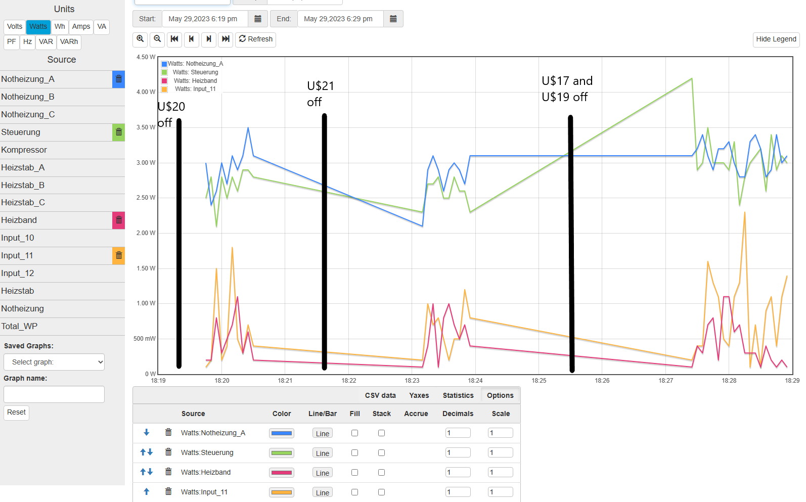
Don’t usually do this but since you appear capable, I’m pretty sure one of the TVS diode matrix ICs is backwards. They are at U$17, U$19, U$20 and U$21. One of them may not be oriented like the others. The TV4 should be on the side of the nearby ADC.
The TVS diodes are not really necessary. They are there for CE certification to increase the static protection of the inputs from 4kV to 8kV. If you find one that is backwards, I would recommend that you just remove it. It could be damaged and installing it correctly now may not solve the problem or cause a new problem.
If you are not sure, please post some high res pictures and I’ll se if I can verify.
I configured all the inputs and graphed one from each TVS. Interesting that the ones from U$17 and U$19 still show phantom readings but considerably lower.
I had reversed one TVS on a test board and got the 2~3 Watt phantom on all channels. So was hopeful, but I still suspect one of them. Can you just remove all 4 of them?
Edit:
If you want to take a more incremental approach, you can remove them one at a time and observe any change. I would start with the U$20 and U$21, then moving to the other ADC.
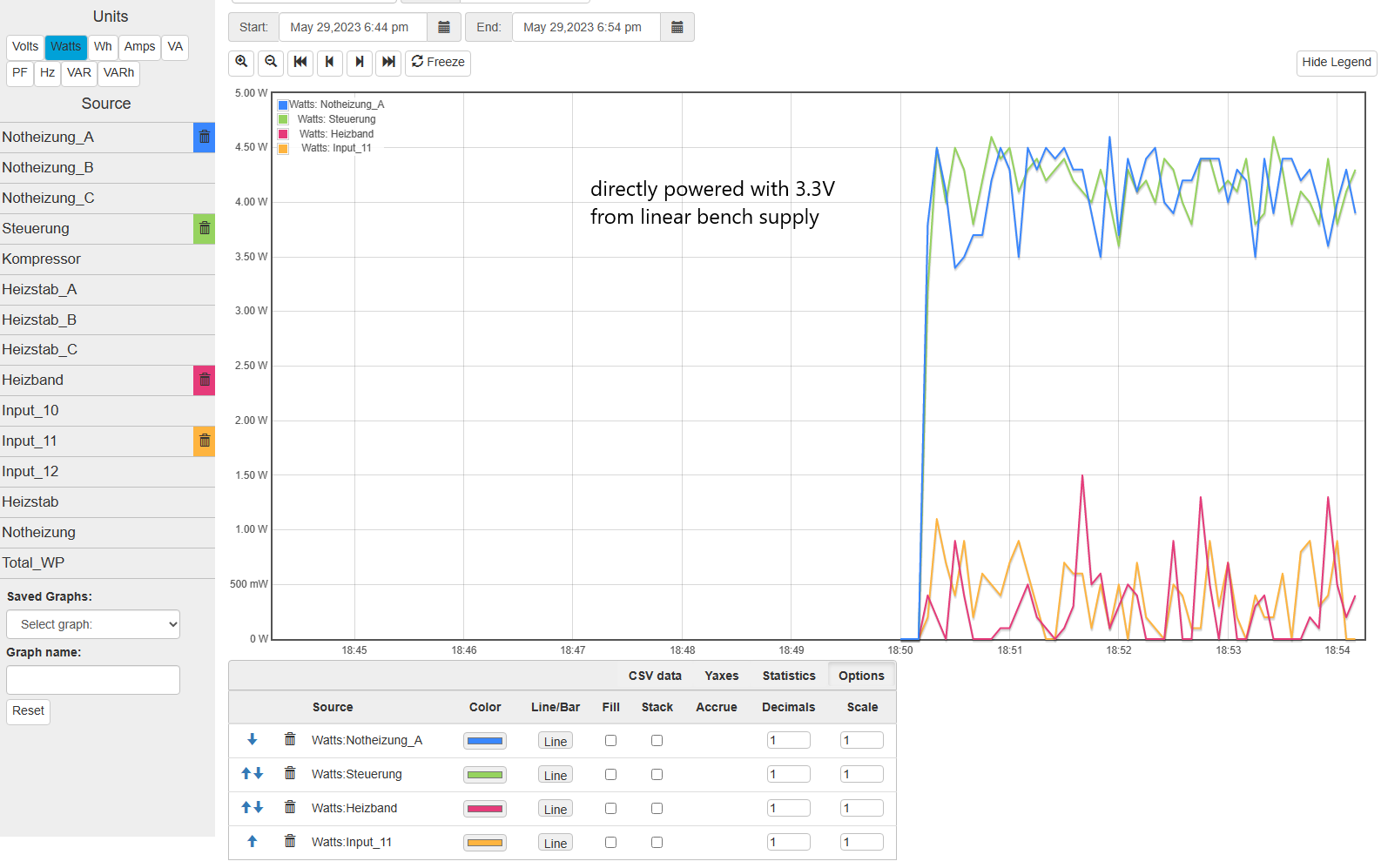
Carried on and powered the IoTaWatt direcly on the 3.3V pins with my linear bench power supply. Unfortuantely still the same, but it rules out the voltage reguator on the NodeMCU.