Thanks a lot overeasy.
We’re about to install for the 3-phase direct reference method. For lab-testing the board of the adapter we first connected two VTs to the same phase of the AC outlet and connected one to the 9V AC REF input and the other though the adapter to input 13/14 which are the ones we selected for the 2 phases.
We’re measuring at the corresponding ADC inputs and seeing the same signals in the oscilloscope. Can’t really tell if there’s a time difference (phase) between them (although I can go back and measure again if needed).
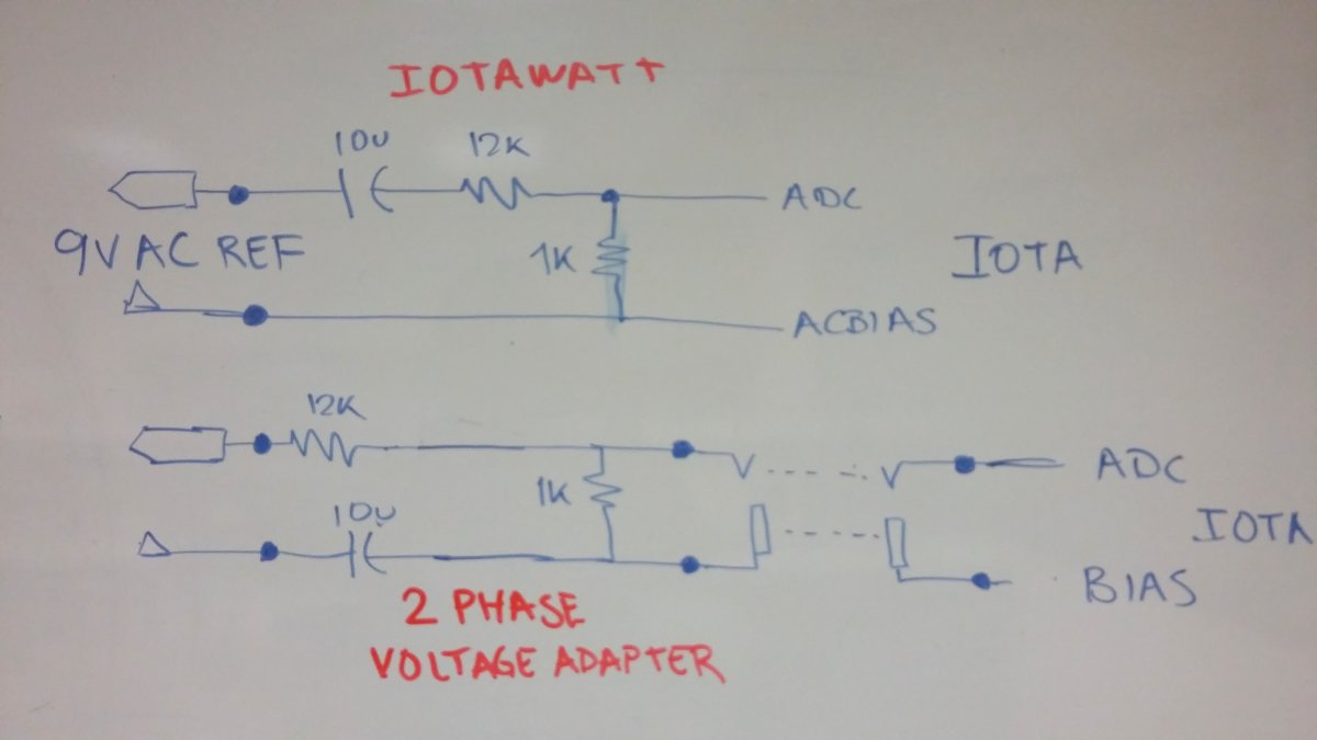
We’re also checking the schematic of the adapter (yes, even after we built it already) and it looks as if the circuit in the adapter is not an exact match to the corresponding circuit for 9V AC REF. The differential voltage measured at the sense 1 K resistor is the same (since the current is the same) but the bias is applied to a different point in the circuit.
Thanks.
This area of the hardware design is something I would like to have another shot at. Suffice to say it works, but the history is colorful. As I see it, the difference between the two is where the 10uf cap is located.
Going way back, IoTaWatt did not use an op-amp. It used voltage dividing resistors to create a bias on each input, including the AC reference. The impedance of the voltage dividing resistors was a limiting factor in the “sample-and-hold” architecture of the ADCs. The 10uf cap helped provide the boost needed to get over the current limitations of the voltage divider. At that time, an additional sample-and-hold delay was being used as well.
With the introduction of the op-amp, all of those problems went away. IoTaWatt became rock solid and all of the caps on the power inputs were removed as well as the 28 voltage dividing resistors. The cost and complexity of the board went down considerably.
But the cap on the VT input was left in place. Call it an oversight, but it was also left in place because there are a lot of DC power supplies that have the same plug, and I wanted to protect against one of them being inserted into that jack. It wasn’t well thought out, and the side-effects of phase shift weren’t well understood. But that’s water under the bridge, it’s there now.
I’ve experimented with both input circuits and found the phase shift to be the same regardless of which side the cap is on. That’s what my reading indicated, but given my lack of training in this stuff, I always try to prove things out empirically.
Once resigned to having the cap, there is a deliberate reason for having it on the other side in the VT adapter. There are some folks who are using multiple IoTaWatt in three phase environments and use simple splitters on each of the VTs to allow using one VT to service two or more IoTaWatt. This all seems to work fine. The capacitor isolates the DC bias so that if the devices happen to share a common ground (powered USB hub for a power supply), they will have isolated bias circuits.
Most of the better VTs have pretty low basic phase shift. The 10uf cap introduces anywhere from 1.4 to 1.7 degrees of shift depending on the VT voltage where the VT itself may be only a fraction of that. I have tried using a 47uf cap and it introduces substantially less shift, and I would like to switch to that if I can find a reliable way to identify the difference in software. Maybe the EEprom during manufacturing testing.
Lastly, larger phase shift isn’t necessarily a problem. When using the SCT013-000 CTs, the lead of the VT is pretty near that of the CT, so lower shift in the VT circuit would actually require greater correction. But the solid core and better Echun CTs that I have been using can be very low shift and a better match for a low shift VT circuit.
Thanks for a very interesting explanation.
I’m now confused with the polarity of the VTs and CTs.
SCT019-000 is very clear regarding polarity; a message along with the model says “This side towards source”.
The SCT013-000 is not that clear, since there´s only a couple of arrows pointing towards the face with printed text (see photo). Additionally , the polarity of the VT (Ideal 77DA-10-09-MI(USA)) is not clear to me and I don’t want to make assumptions.
I would usually consider my reference to be the SCT019 and then plug the VT whatever way it gives me the correct polarity in the status tab of the IoTa, but honestly I’m confused now.
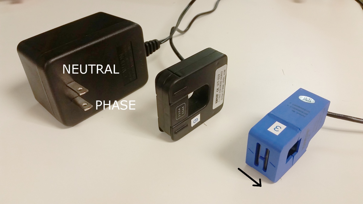
For the SCT013: The arrow points towards the text, as shown in the photo. What’s its meaning?
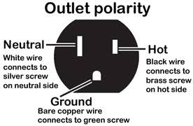
For the VT: I’m assuming the shown polarity in the photo since I would plug it into the socket (see photo) with output cord pointing down (although I think it should be with the cord pointing up).
Thanks!
We figured it out. We were having some problems that made us really doubt our understanding of the configuration, but we already made some lab measurements to sort it out.
Do you mean you figured out the Polarity or the Power Usage (eg Mains and Solar readings vs IotaWatt readings)?
No, sorry. That was related to my immediately preceding message where the polarity of the CTs and VTs wasnt’ clear to me. Sorry about the confusion.
All good. I wasn’t sure if you had the same original issue with Measured Mains being 50% too high as that is what I am seeing. That said my initial problem is ensuring my VT is working as planned.
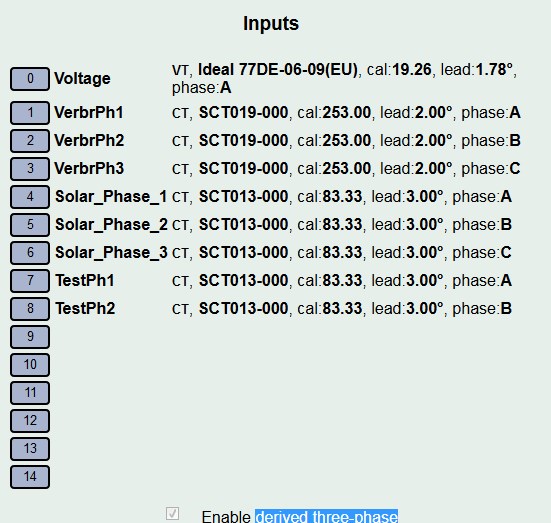
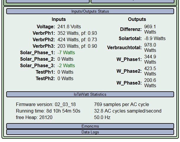
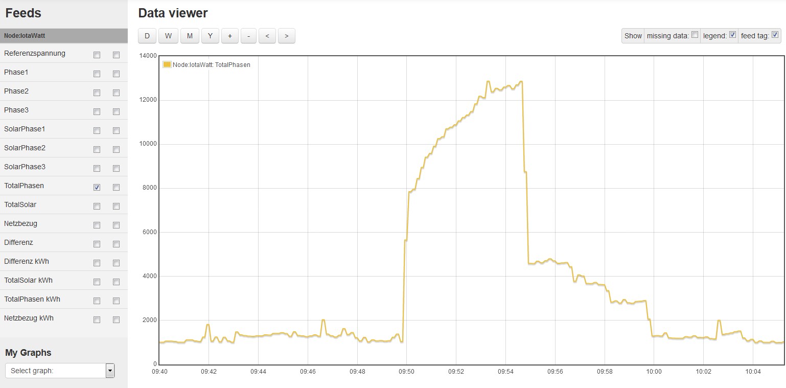
Hello, I’m back.I have now measured the current for about half a year. Unfortunately, I had a break in October for several weeks. Thanks to the help of Overeasy, the problem could be solved. I then switched to self-consumption measurement about 4 weeks ago.I now measure the current directly on the 3 phases with 3 CT type SCT019-000. With another 3 CT type SCT013-000 I measure the current that comes from the solar generators. Enclosed a picture of the recorded data. The solar power is recorded correctly and corresponds to the values that I can read on the solar generators. But the current in the phases is too high by a factor of 2. I can understand this well during the night, when no solar power is generated. The electricity meter from the electricity supplier shows only half as much power as iotawatts.The CT are connected correctly, the reference voltage is also on the correct phase.In my understanding, the 3-phase current measurement of iotawatt does not have to be correct. I suspect that the derived three-phase method does not work properly. Am I doing something wrong? Thank you very much.
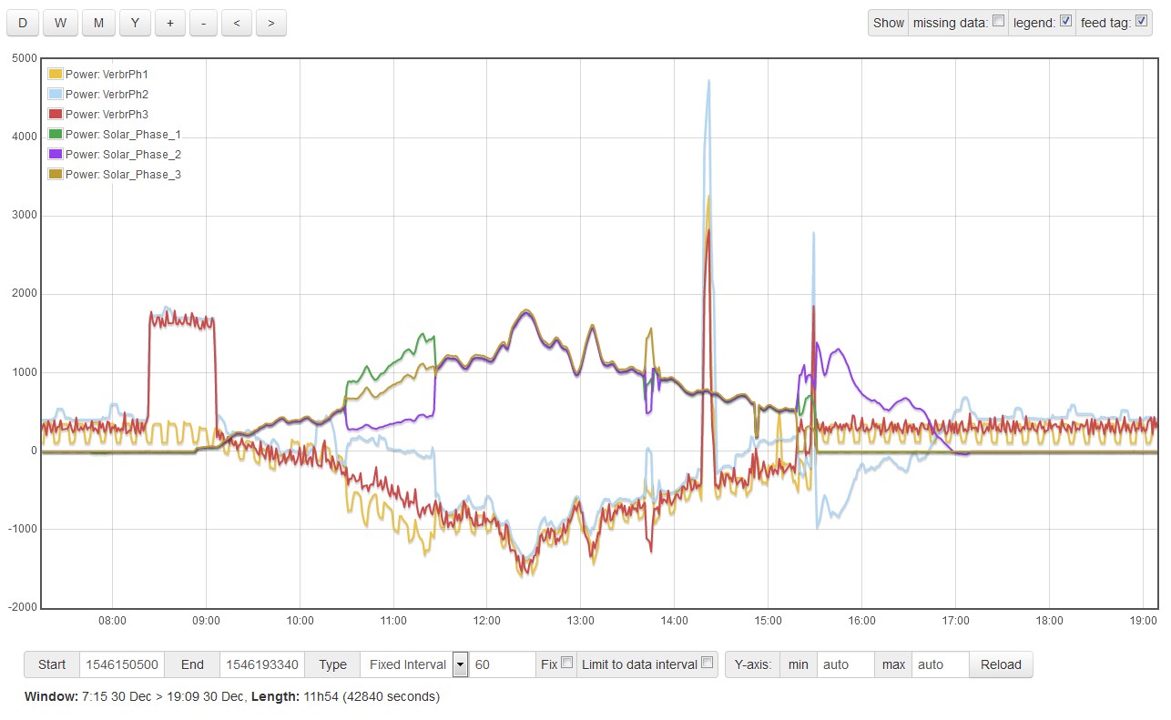
You use the terms “current” and “power” seemingly interchangeably,while they are completely different things, especially in this three-phase environment. So its not clear to me what the problem is, or even there is a problem. I don’t see any large discrepancies in the graph that is posted. The power being exported appears to be in the same range as the power generated minus what looks like about 900 watts of baseline load. There are a couple of periods when the inverter appears to shift production to favor one of the phases over another, but the net appears reasonable. I speculate this might have something to do with voltage.
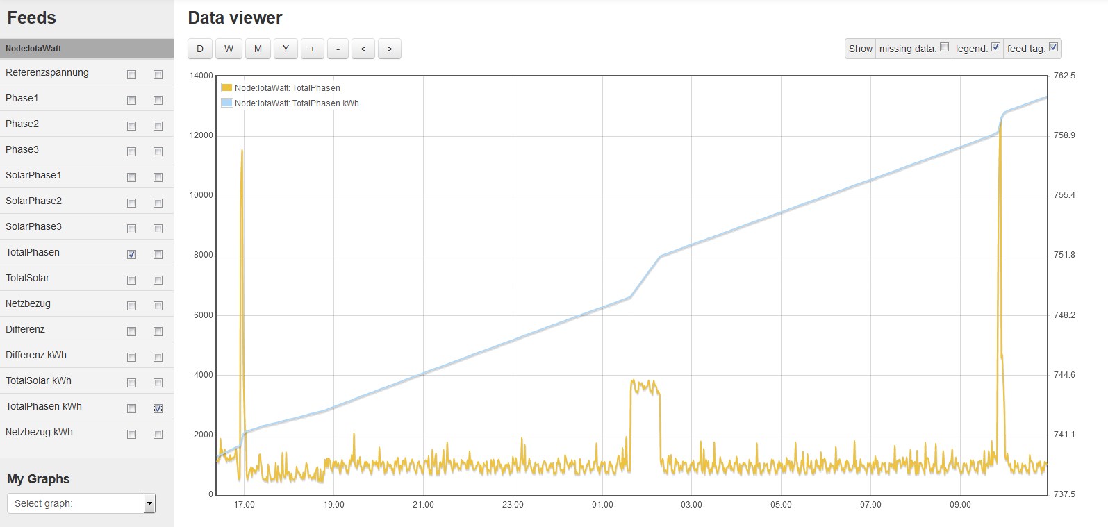
When you say the IoTaWatt is double the value of the meter, is that Watts, kWh, or Amps? Your baseline loads do oscillate, so I would be interested to see data detailing the kWh recorded by the meter vs the kWh recoded by IoTaWatt for an overnight period where there is no solar generation. At your baseline consumption, You should use in the neighborhood of 10 kWh from 17:00 to 09:00. You could rea$ the meter at those times and then examine the “energy” graph from IoTaWatt for that period to see what it records. If it is off by a factor of x2, that should be pretty clear.
I don’t understand how a problem with derived reference configuration could produce the result that you seem to be describing.
sorry, it is a translation problem
on low solarproduction the 3 inverters are feeding on only on one or two phases
I mean kWh
this baseline load is about 450 - 500 watts. I can measure it with an app (energy meter reader) from the beam-light of the energy meter. An baseline load of 900 watts is not possible as there are no such big consumers at night. I could measure it over the night, but I think it is not necessary.
I don’t have any details of your equipment, but typically the light on a meter blinks to indicate that some number of Watt Hours have been consumed. So in that case the light indicates energy used. Comparing that to Watts, or power, is not possible without doing it over a fixed interval.
So that’s what I’m looking for here. All I have to go on when I estimate your baseline load is the screenshot of your status display, which is an instant in time. Clearly your phases 1 and 2 are not constant so 900 Watts could be the extreme. I just don’t know. When you let IoTaWatt accumulate the energy used over a longer interval, and compare that to the meter’s own calculation of the same, a clearer picture will emerge.
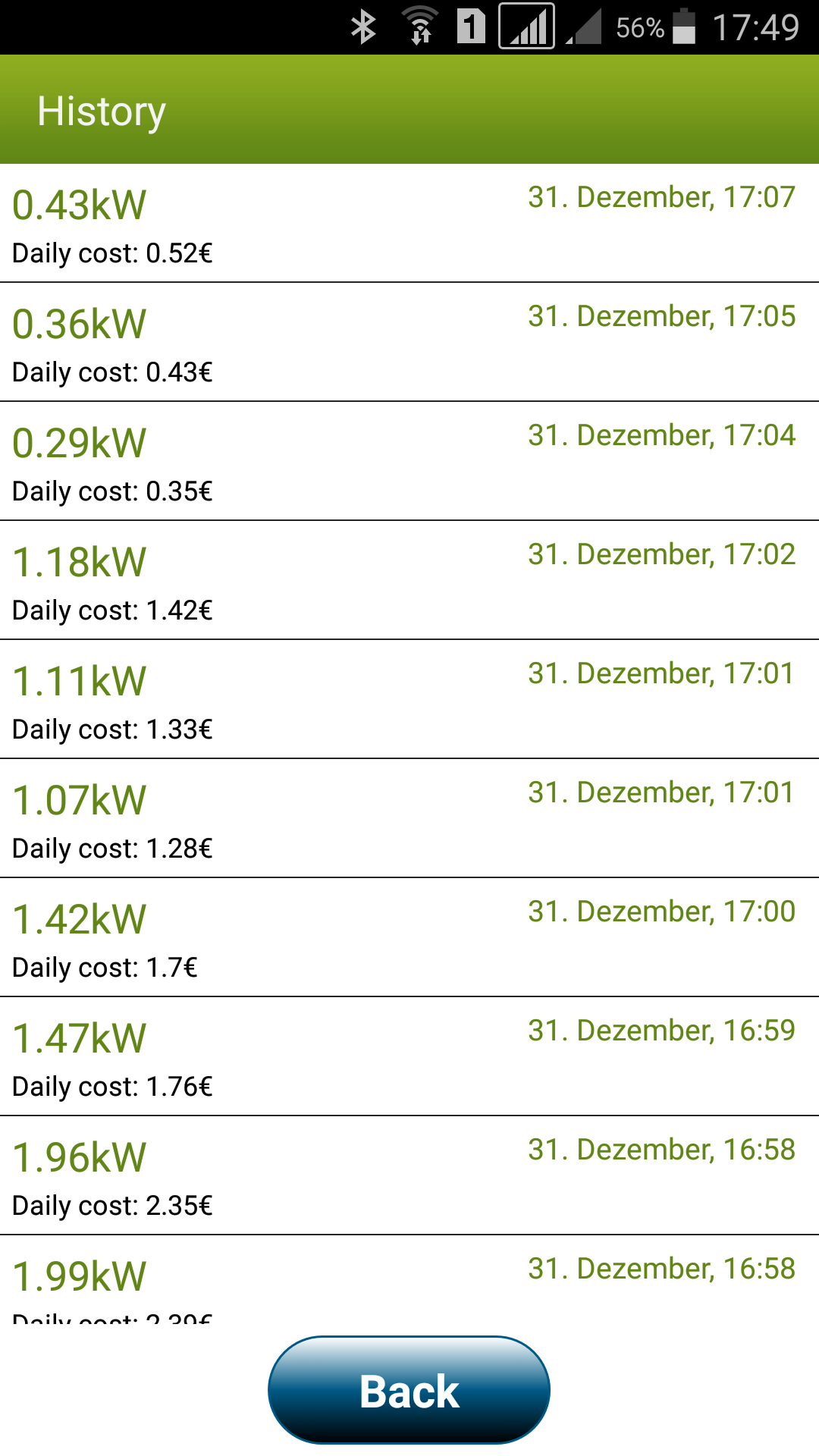
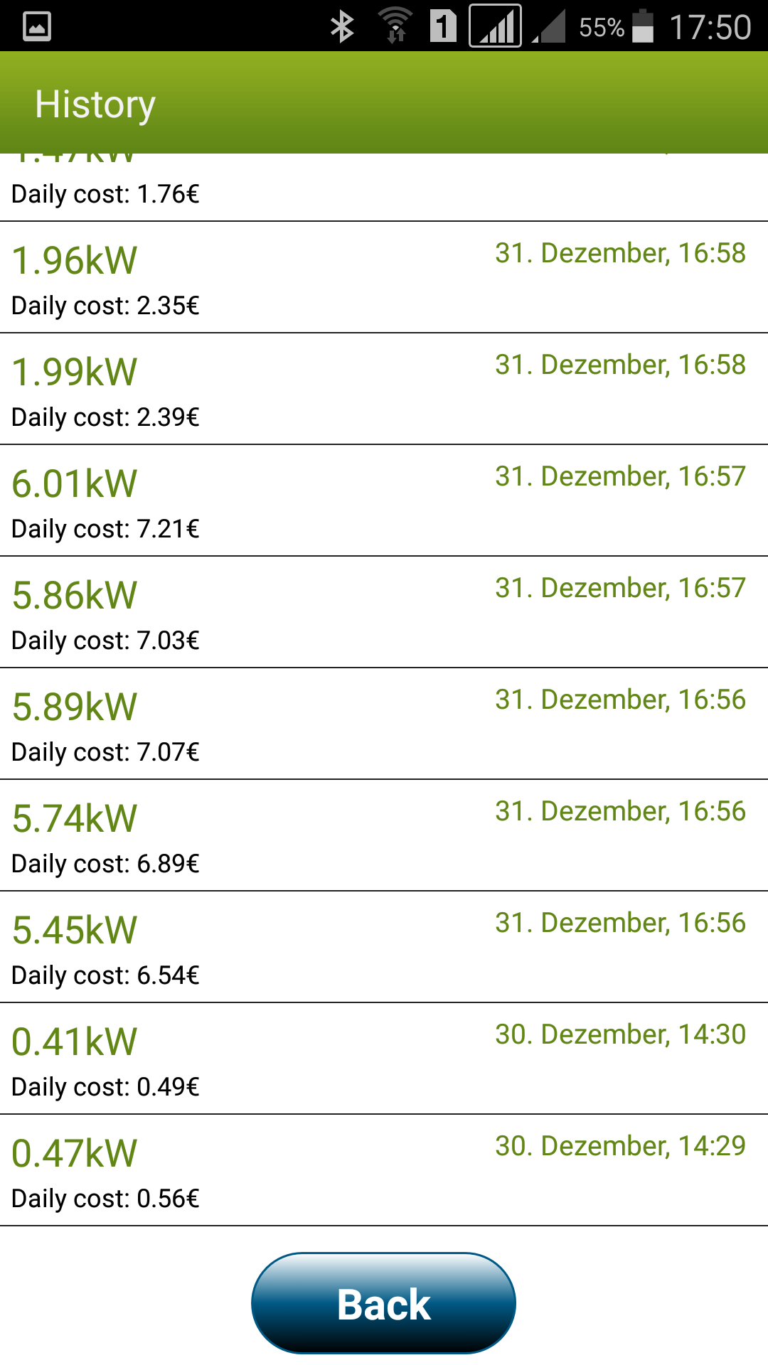
250 pulses/beams are equal to 1 kWh. The App measures the time between beams and can then calculate Watts. It works quit good. Following the measurement off the App and what iotawatt measured:

Some comments:
16.54 Compressor started
16.57 Compressor stopped
16.59 Switched off 3 Sodium vapor low pressure lamps (translation correct?), each 250 Watt = total 750 Watt
17.00 Switched off 2 lamps, each 250 Watt = total 500 Watt
17.02 Switched off main switch, the remaining consumers are offices (printers, computers, telephones, etc.)
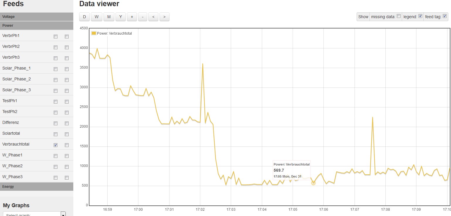
The reduction between switching off 5 lamps (1’250 watts) is on the energy meter (App) only about 800 watts. I have only one explanation, it has something to do with blind energy. But my knowledge is not big enough to judge this process.
You have the advantage of being able to examine all of the components of this experiment, while I am left with your assertions about the standard being put forward. Looking at the data, it appears you are not just in the ballpark, but nearly exactly correct that the app is reporting half the power that IoTaWatt is reporting. That’s hard to do. Is it possible that your meter pulses 500 times per kWh? This is why I want to compare the numerical display on the meter with the kWh total from IoTaWatt.
Another possibility is that you have checked the “double” boxes in configuring the CTs.
Those are two possibilities that are more credible than “blind energy” which I will confess I am unfamiliar with.
Correction, is it possible that your meter pulses 125 times per kWh?
First of all, I wish everyone a happy new year. I thank all developers for their work with iotawatt.
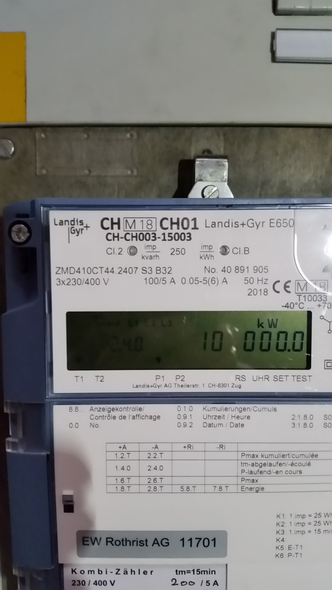
First a picture of my meter from the energy supplier:
And here the numbers of the energy meter:
31.12.2018, app. 17.15: 272 kWh / 193 kWh (Tarif 1/Tarif 2)
01.01.2019, app. 09.45: 275 kWh / 199 kWh
Total: 3 + 6 = 9 kWh in 16.5 hours; 0.55 kWh per hour
As we have also a beam for kvarh I made measures as abouve but with blind power:
| Time | kW (from kWh) | kW (from kvarh) | |
|---|---|---|---|
| Main switch off | 9.42 | 0.73 | 0.37 |
| Compressor and 5 lamps on | 9.50 | 4.03 | 3.25 |
| Compressor and 5 lamps on | 9.51 | 5.21 | 2.79 |
| Compressor off, 5 lamps on | 9.55 | 2.3 | 0.41 |
| Compressor off, 2 lamps on | 9.57 | 2.19 | 0.47 |
| Compressor off, all lamps off | 9.58 | 1.43 | 0.47 |
| Main switch off | 10.00 | 0.68 | 0.41 |
And here iotawatt:
I would be happy if someone could explain me how it works with blind energy (kvarh).
And you.
I see the 250 imp/kWh. That is an interesting meter. It looks as if you can read kWh for each phase (L1-L3). That might be useful. With the data you have posted, it looks like the meter and IoTaWatt differ by exactly 2x, which tells me there is a configuration issue somewhere. I don’t think it has anything to do with VAR. What you are calling “blind power” is “reactive power”. You can learn about that from the internet. Wikipedia has good discussions of how that all works. IoTaWatt can and does measure reactive power, but that doesn’t have anything to do with the discrepancy we are trying to resolve. It would not explain a constant 2x variation.
I would like to see your config.txt file for the IoTaWatt. You can download it from the file manager and upload it to the forum. If you are using EmonCMS, you should remove the write-key before uploading.
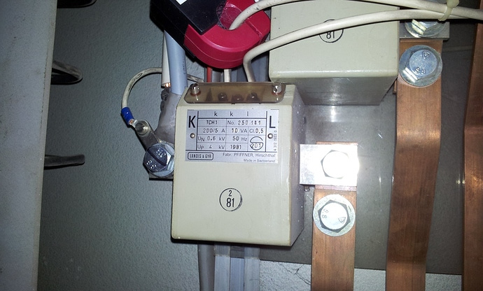
In looking at your meter, and from what I can find online, it uses current transformers like IoTaWatt to sense the current. On the upper part of the meter there is a designation of 100 / 5A, which I believe says it uses CTs that output 5A at 100A primary.
On the bollocking section, there is another designation of 200 / 5A where the 200 is hand written as if by the installer. This is a 2x difference. It’s a stretch to think that your meter is installed so as to record only half of your actual usage, but something is wrong somewhere.
You have been supplying data with loads like a compressor and sodium lights, which are not purely resistive loads. If you have a significant purely r3sistive load, like a toaster, it would be very helpful to see a plot of IoTaWatt power for the phase it is on, while switching it on and off. The nameplate power of the appliance would be needed as well.
1 Like
You got it, you are right. The energy meter shows only half the amount. The 100 / 5A would be the correct current transformer, but on this installation are 200 / 5A transformers:
Thanks a lot for your help.
2 Likes
Congratulations on this detective masterpiece! Very impressive how exactly you looked at the picture and researched the details.
1 Like
dear all,
i was working some months with derived three-phase configurated IOTAWATT.
just now i have 3 voltage transformer to measure GRID voltage but i can t configure IOTAWATT to work with them, because can t remove the thick/coma from Enable derived three-phase selection.
could you help me to fix my problem ?
thank you,
laurentiu
The “Enable Derived Three-Phase” selection is not modifiable as long as there are input channels assigned to phase B or C. If you change all input channels to phase A, you will be able to uncheck the box.
Once you do that, and configure additional VTs, the Mains Phase selection will disappear from each input configuration and you will instead select the name of the VT that corresponds to the input’s phase in the VRef selection.