thank you !
it works, i can configure, but new problem:
as i use 3 transformers /VT now, i was configure first VT as usual, for the first phase, V; is OK.
I configure the second and third one same as first, but nothing when try to calibrate; to be clear,for the No. 2 and No. 3 transformers, exit that is measured in IOTAWATT are in serial with 330 ohm, as the channels for input is 20 ohm .
measured voltage is at the input of an divider which consist from an rezistor 330 ohm serial with the burden rezistor from channel 13 and 14 of IOTAWATT; as this is formed in those channels a divider that must be OK as input.
in reality is not working at all, is showing is this channels 0 volts all time.
can you advise mr what to do ?
mean time i will try to find a electric drawing from inside input of IOTAWATT to understood better.
THANK YOU !
laurentiu
Couple of things:
I would need to see your config.txt file or at least a screenshot of the inputs setup menu to verify things are correct.
Although it should work, and does work in several early installations, this voltage divider technique was abandoned awhile ago for several reasons.
The 300 ohm resistor will dissipate quite a bit of power. If you do the math, a little over 300 mW. So if you are using a 1/4 watt resistor, that won’t do. In the past I have used different combinations to deal with the power. Three 100 ohm 1/4W resistors in series, or a couple of 680 ohm 1/4W in parallel. I also made sure they were fully exposed so they could cool. I had some infrared pictures of one of these in operation and they were noticeably warmer than everything but the ESP8266.
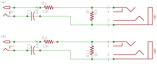
The adapter that is described in the GitHub site actually emulates the channel 0 circuit with a 12K and 1K resistor voltage divider. This is connected to the input with the burden removed.
The next version of IoTaWatt, due out in April, has inputs for two additional voltage channels which, when used, replace the channel 13 and 14 inputs. They use the same circuitry as channel 0. Contact me when it comes out and I can arrange an upgrade at nominal cost.
dear Sir,
clear understood your explanation regarding principle of measuring.
i have ability to deal with situation regarding modify channel 13 and 14 and removing burden resistor and what will be necessary.
please , try to give/send me electrical drawing with necessary modification and i will do it.
for next release of IOTAWAT, i will be glad to have the upgrade that you mentioned.
i have another question if you could make me clear:
IOTAWATT hawe 14 inputs plus VT original input.
at OUTPUT, i can configure, based on the declared INPUTS a number of maximum 29 line/ outputs.
do you think that is possible to increase this number of OUTPUTS ?
I need to increase those OUTPUTS to export more data on an EMON PI locally running in a RASPBERRY machine.
thank you for your answer,
laurentiu
That is an artificial limit imposed in the configuration application. You can change it by modifying the regular expression used to check the name at about line 1812:
  scriptEditNameList = [];
  scriptEditNamePattern="^[1-9]{1}$|^[1-2]{1}[0-9]{1}$";
  scriptEditNameTitle="Name is Emoncms Input Key 1-29";
  editScript();
You are interested in the scriptEditNamePattern, which allows the numbers 1-29. The expression [1-2] limits the name to 29. Changing that to [1-3] should allow up to 39 and so forth.
Understand that you are in uncharted waters when sending that volume of data. It will take more time and memory to send larger frames to Emoncms. I believe Emoncms accepts up to 99.
thanks a lot !
hope to have all electronic components for the end of this week to can finish this task;i will return to you with necessary file, data and result.
laurentiu
hello Bob,
just succeed to modify input to IOTAWATT, means put 3 VT as in the drawing provided previously, for a three phase system -particularly my system is an ESS system, 3 phase.
everything is OK for the moment , working fine.
checking also for the software modification how i was asking - for the moment i just identify line number for modification. as soon as i will proceed , i will let you know for the result.
just now, need more than anytime to measure 2 DC measure: DC/voltage of battery - maximum 58 Vdc and amps of battery +/- 500A maximum, at charge and at discharge.
do you thing that will be possible in future ?
thank you,
laurentiu
Great!
No. IoTaWatt is strictly AC. You will need other equipment for that.
hello Bob,
please, tell me which kind of equipment you have in mind for DC .
i m learning continuously
thank you,
laurentiu.
Sorry, I’m not a good source for that information. You might try asking for advice on the open energy monitor forum. They have some electrical engineers over there with broader knowledge.
hello Bob,
today i was continuing with wok for my prefered tool: IOTAWATT
as i was asking in the past, i modify the configuration line, as you was explained me before:
- in fact we are talking about line 1802 and line 1803 ; i make necessary modification in those line and after that i was press: upload.
apparently, even after restart those 2 lines are looking same as before modification, but i can continue to write new lines as i was needed.
do you think that is correct my work as i explain ?
Not clear what you are telling me, sorry. I think you are saying:
You modified the lines of code but do not think it uploaded. I don’t know what tools you are using. I like to use the IoTaWatt’s own “File Manager and Editor”. After making the changes, just use ctl-s to save it.
If you are now able to add keys greater than 29, then it does sound like the changes were uploaded. Again, use the file manager and editor to look at it. The index.htm config app appears by default in the editor when you run it.
hello again,
- i use the File Manager and Editor from IOTAWATT.
- after i was making modification that i need, i press UPLOAD
- i was restarting IOTAWAT
- recheck lines that i was modify previously and, it was as original , not as modified lines
in this situation, i was able to write more than 29 lines as the beginning, to save all of them and to continue working.
do you thing that need tp work in another way?
thank you,
laurentiu
heloo Bob,
my mistake !
as soon as the modification is not saved or UPLOAD ed, is NOT working more than 29 lines.
means, that need to proceed in another way . i don t know how to proceed.
upload in the file manager uploads a file on your computer that was previously selected with the browse button.
When you edit a file with the editor, use ctl-s to save the file.
it works !
mistake it was from my part, that every time is not saved the modification before to UPLOAD !
ufff, not easy …small job
thank you !
hello Bob,
i have a question relatet to Iotawat:
- do you think that is possible to have multiple VT ?
the question is related to the fact that in an ESS system, i would like to have 3 VT at the input of the system that will measure the input voltage from grid and another 3 VT at the output of system, who will measure the voltage at the exit of system, going to house.
i was asking this question because, today i was checking the recording of my system and i don t see anymore that the grid was missing for some time; actually , my system with 3 VT is checking / measuring the voltage at output of system, in the part where energy is delivered to house.
thank you,
laurentiu
If I understand what you have done correctly, you already have 3 VTs. You have made a VT adapter to add 2 additional VTs and connected them to input channels. If you make more adapters, you can add more VTs. Any input channel can be configured to be a VT.
hi Bob,
yes, clear what you explain: already have 3 VT arrange how i was explain already in my previous post and is working fine.
i was asking about multiple VT , because as per example , i need 3 VT more; at that point i was not sure that all mathematics inside IOTAWATT support configuration with more than 3 VT.
thank you again,
laurentiu
No problem. You can configure as many as you need. There are no limitations.
hello Bob,
as usual, i m happy with YOTAWATT; since we can select time for recording, is more nice.
i need to ask you some questions:
- do you think that is /will be possible to can see on the grafic the current ( or another values ) in three phase system that is decalate each at 120 degree? hope that is clear what i want to ask - all three phases don t have same origin, there is an angle between them.
- for the moment, my Iotawatt have configured 14 inputs and 30 output, no communication with emoncms, i m satisfied with readings but for the part when is displayed ( outputs ) measured value and what i see at output ( as measured values ) is change to quickly.
do you think that is a solution to have something as filter for each input or output to can adapt response time or is another solution?
to be more clear, time to time i need to compare values of measurements from VICTRON with outputs values of Iotawatt as numeric value and is near impossible due to the rapid mooving of them from Iotawatt.
thank you,
laurentiu