It is not currently available.
That ESP32 is certainly a solid upgrade. Would the use of it give improved resolution of data verses the ESP8266 currently? What I mean is if there is a brief power blip would it be able to capture that and record it?
i have studied the new pictures of the ESP32 version. It seems like the new version use mora than one cs pin for the SD and you use 2 pin more for the expansion board for using 28 channels, and maybe this is the reason because there is no enough pins for use RJ45 version. Is it true?
maybe if we don’t use the new expansion board and use the SD card as the old version, can we use RJ45? best regards and sorry for to be so intense. But we need 150 iotawatt with RJ45 and we are currently working on this(if you would have this version we will buy it, but there is no version and we are trying to implement it)
best regards
It’s not that I don’t want to add ethernet, I just can’t see how it can be done.
You are correct. The SD is now MMC, which uses 6 pins. It could be run with standard SPI, which uses 4 pins, so assuming the second SPI can be utilized, and that the pins can be relocated, That frees two pins.
The are two additional pins being used for ADC CS on the expansion board. That’s another two pins for a total or 4.
The LED is currently using two pins. An I2C expansion board could cover that. Two more pins, now we have 6.
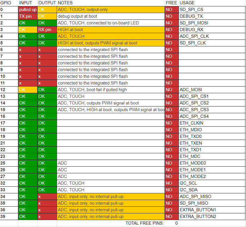
GPIO34, 35, 36 and 39 are available but are input only., so can’t be used to reroute existing functions.
The LAN8720 PHY requires 9.
If the SD were moved to the same SPI as the ADCs, you would pickup three more, but the way the ESP32 firmware works is that one of the processors samples continuously, monopolizing the SPI. To do SD I/O would seriously degrade both sampling and SD access to the point that except for having ethernet, there would be little advantage in going to the ESP32.
SPI based ethernet might be possible. That would require degrading the SDcard from MMC to SPI and sharing it with the ethernet. That might be the only viable option if it’s possible. I haven’t really looked at it very closely.
In terms of the project and what folks seem top want, the expanded inputs is easily the top priority.
2 Likes
Hi Bob,
I just wrote a table, with possible pin mappings if you wanted to have ethernet without having to reinvent the wheel. You’ll notice I have not used GPIOs 1 or 3 because they could be used for serial debugging, but they could be reassigned for MMC access to the SD card. Also, in case you want LEDs, I would use an I2C IO extender (much slower changes needed) to drive them along with other possible buttons.
I know your design is well underway, but the problem we have in Europe is our electrical boxes are much smaller and are pretty crowded, meaning WiFi is a bit more compromised.
As a bonus, if we could somehow add isolated PoE, that would greatly help with certification, as the iota’s power supply could be outside of the electrical box. With the added benefit that if your PoE supply is on an UPS (as mine is) you could be notified by the iota when you have a power cut 
Thank you for being so supportive!
OK, that’s interesting. Couple of things:
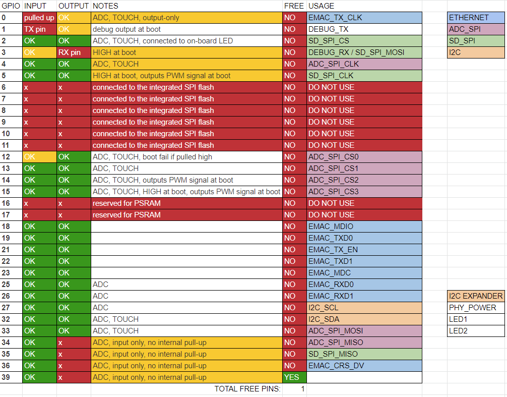
I use the ESP32 WROVER with 4Mb PSRAM. It’s not obvious in the docs, but uses GPIO17 internally as CS for the PSRAM on the flash SPI. That’s shown on your diagram as ETH_CLKIN. What is that? My limited research on the LAN8720 PHY describes it as “NC - Osc. Enable - 4k7 Pulldown” If it’s an input, maybe it can go to 36 or 39?
I also show GPIO0 fixed as “EMAC_TX_CLK”. Can you clarify that?
Finally, if GPIO0 is needed for EMAC_TX_CLK, where can the SD_SPI_CS go?
One thing that comes to mind is that using 4 GPIO as CS for the ADCs can be done with three using a decoder. Two GPIO specify the ADC (0-3) and the third is the actual CS. It would require more pin setting in the sample routines and would have a small impact on sample rates, but that’s not a big problem as the ESP32 is a little faster than the ESP8266 anyway. But it does involve adding yet another chip.
So far we’re talking adding an I2C GPIO expander (most are pretty large 16 output affairs) and a decoder chip for ADC CS, as well as the PHY, RJ45 connector and probably a handful of caps and resistors. I don’t even want to talk about PoE.
This is basically back to the breadboard. It’s probably a couple of month project at best to get to a working PCB, and the enclosure would need significant mods, if not a completely new mold ($15,000).
Just to put some of this into perspective.
I’m not pressing hard for either Ethernet or POE but you could just provide a set of headers from the magnetic jack and a set of headers for the 5v and ground, where a “hat” could be added for POE. (See Raspberry Pi 3/4).
If you wanted to include a POE circuit, this works well and provides a decent isolated supply.
Hi Bob,
I had responded you but I took a better look at the ESP32 datasheet and there were some inconsistencies in my message. This is what I found out after reading the datasheet:
- Looks like the ethernet clock signal cannot be used in a random pin. Only GPIO0 or GPIO17 Only some of them are fast enough, so using GPIO0 to generate it should work (ETH_CLOCK_GPIO0_OUT).
- Because the ethernet PHY should not be enabled until there is a valid clock, a PHY_POWER output is needed, but it is a slow signal, so the expander can be used.
- The datasheet, however, states that “MDC, MDIO, CRS and COL are slow signals, and can be mapped onto any GPIO pin through the GPIO-Matrix”. Meaning we can move EMAC_CRS_DV to an input-only pin.
This is the resulting pinout:
Let me know if this looks at least a litte bit more feasible.
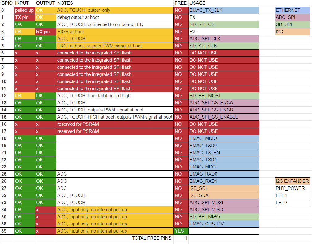
I don’t think I could develop or maintain firmware without RX always available. SD_SPI_MOSI would need to be moved. Using the output decoder for SPI CS could gain a pin.
Have you ever tried getting a PHY to work with an ESP32 or used the GPIO MATRIX?
Hi Bob,
Thanks for answering so fast. We could always go back to the encoder solution:
And to answer the second. Yes and yes. My home runs on these little things:
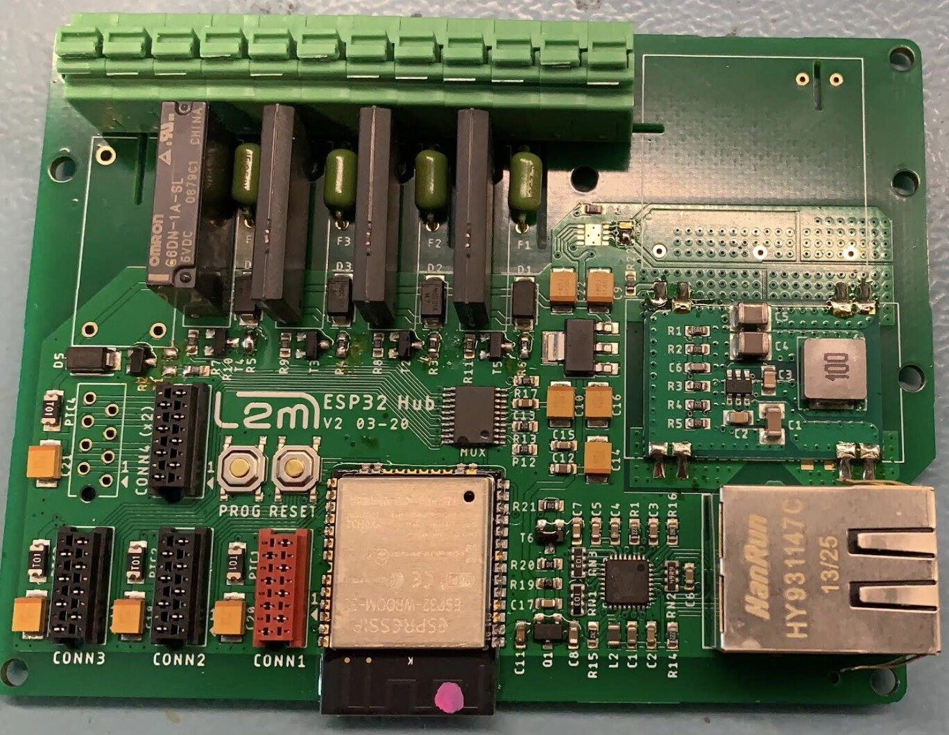
As you see, there is no clock for the LAN8710, that is because I am using the ESP32 as a generator. It also has “homemade” PoE, with a DCDC that can go from 7V to 28V. I am certain the GPIO matrix works for SPI, because on one of those controllers (CONN3) I have a MCP3208 running myself to do some tests.
However: it is running ESPHOME. ESPHOME is really nice for the things I need to do in my house (controlling buttonpads, switching on/off things or sending IR commands to my AC or ceiling fans) but it is true that I have never tried to sample 32 SPI channels hundreds of times per second while calculating currents, voltages, powers, energies, storing all of those values in an SD card and serving a webpage. That… I think you might be the only one that does that.
Do you have a schematic for that board?
The one I showed? Sure!
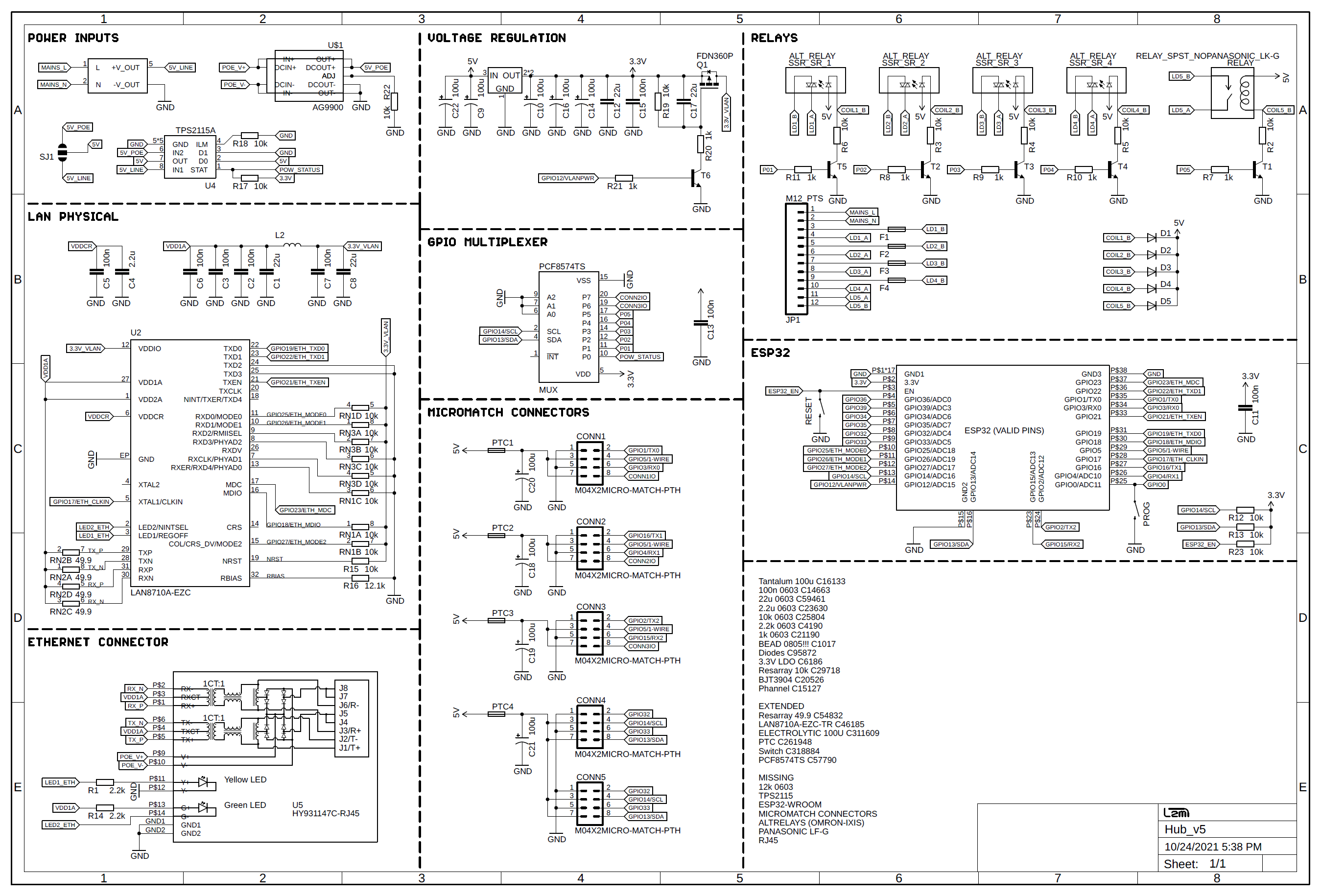
However, this is NOT valid for WROVER module (I do use GPIO17 for generating the PHY clock)
That’s the situation in the energy monitor world. The electrical engineers are very knowledgeable about signal processing and building hardware, but don’t have the programming experience to make the device more versatile or useful. I’m not throwing stones here, I have the same issue in reverse. I have only basic electronic literacy, and can’t do complicated digital electronics, much less any type of analog circuitry. You probably figured that out looking at the IoTaWatt schematic.
My approach has been to get really high sample rates, and do the rest in the digital realm. Anti-aliasing isn’t really a problem when you are actually measuring several levels of harmonics. Phase shift can be easily corrected when your samples are half a degree apart.
So my hesitancy with making these changes is that I will get into electronic design problems that I simply do not have the skills to debug. If the ethernet doesn’t work, or worse works sometimes, I don’t know where to start debugging it. Having this schematic is a start, but there are a lot of details there.
The voltage regulation is an analog circuit. I’ve struggled with trial and error designs to clean up the sampling bias. My ESP32 design has a crude filter system that I just built by watching the output on an oscilloscope. But you get to the point where the scope probes are introducing more noise than you are filtering, yet it should be cleaner still. Your regulator here uses huge capacitors for smoothing, maybe because you are driving relays, but you also seem to have low-pass and high-pass filter caps in there. Then there’s a RC circuit feeding a transistor switch that runs a MOSFET switch to turn on the vlan power. I can copy that stuff, but I have to say that I don’t really understand what problem all of that solves, or how it solves it. Just like an EE may not understand why something I’ve programmed has to be so complex.
So we can continue this chalk talk, which has been interesting and productive for me, but unless you are interested in and have the skills to do some of the electronic work, I’m in over my head. If you are not at all interested in the WiFi, the firmware that I have now would only need to be modified slightly to use a GPIO expander, a decoder for the ADC SPI CS, and switch to one data line SPI for the SD. Not a big deal. You would potentially have a working ethernet unit. With the Ethernet RJ45, it would need an enclosure mod. The way the mold works, the rear face where the two additional VT jacks are can be changed out for a different configuration. Probably less than a $1,000 for that.
Think all that over and let me know how active a roll you want to play in this.
2 Likes
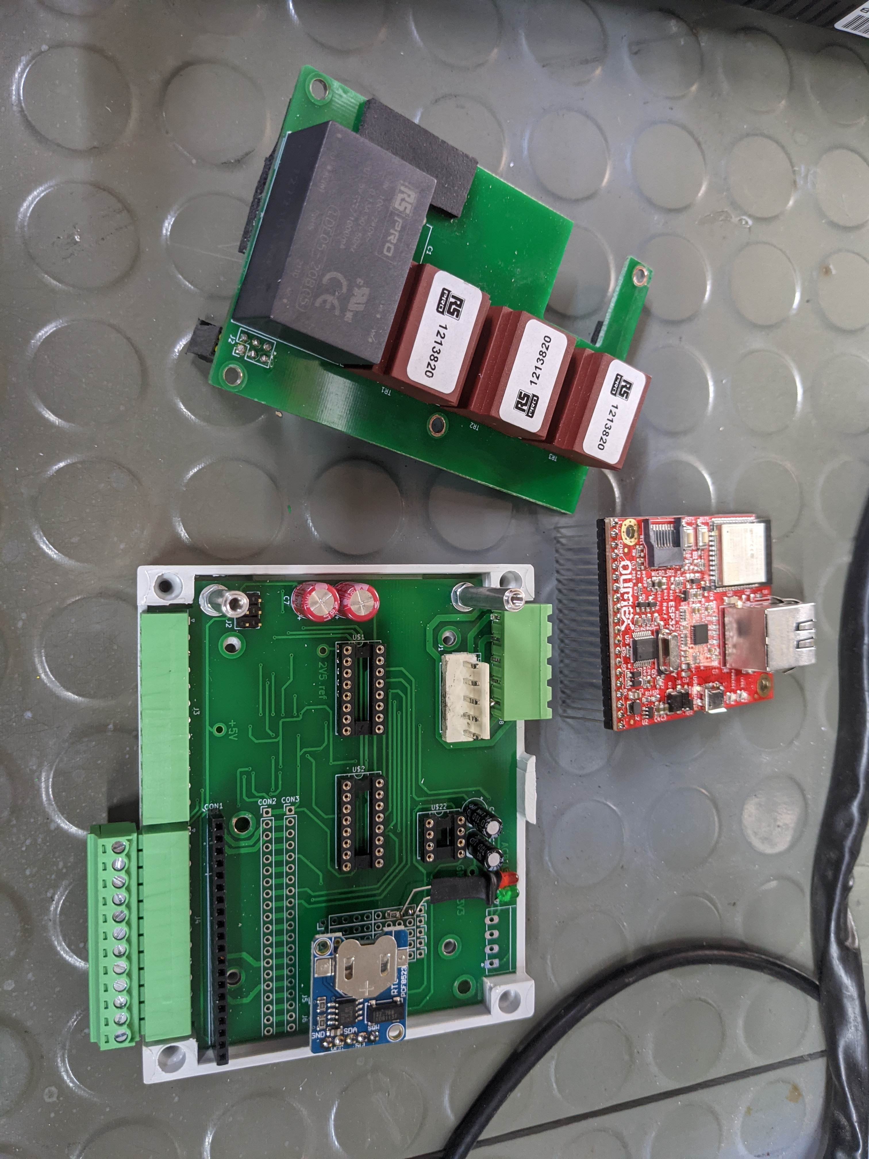
this is our project. We are trying (like @Lemus ) to make a DIN rail case iotawatt with ethernet.
We are trying to use olimex esp32-gateway for our protoype.
The case we are using is a standar buyed from rs component.


we have problems trying to convert old source code from esp8266 to ESP32. By the momento we are not able to compile the code because a lot of libraries shows errors.
thnaks for this amazing project
2 Likes
I get what you say, I have the problem you describe. I do analog design (signal conditioning precisely) for living but I do not have the software (or time to get such expertise).
I do like your approach though, and it is something we do plenty of times. Many times it is better to just get a faster ADC (when possible) and do signal processing on the data.
The other reason why I liked IoTaWatt is because it is UL certified, and having gone through the process plenty of times I know your “pain”. Said that, adding PoE will increase the difficulties of doing UL if this would ever go inside a panel (if it is even possible). I like that right now it can be made so that it is a completely isolated.
Now, that said, and although it would increase the price (which I would be willing to pay) is you could have 2 ESP32’s (or 1 ESP32 and another micro) and isolate them using UL rated reinforced isolators. This way you could have all the measurements taken care on the side that is close to the live parts, use all the GPIO for the ADC selects, ADCs, and any other control you need and then use SPI over the isolation barrier to send data to the ESP32 and use that one with Ethernet…
Many things are possible. Adding parts needed for less than 10% of use cases increases the cost for everyone. Having multiple configurations also increases costs and the difference (if allocated only to the variant) would probably make the Ethernet version much more expensive. There are small and cheap wifi routers that can usually provide the conversion for less than it would cost to add the capability (if the cost is only paid by the people buying that version).
Does the ADC on the ESP32 mean that in theory external ADC chips are not needed? I guess it limits the number of clamps possible, but simplifies other parts of the design?
IMHO, The ADC on the ESP32 is really not all that great in terms of accuracy, linearity, etc… Using a dedicated, high quality, external ADC chip makes more sense.
1 Like
I continue to use external. Anecdotal reports are that the internal are not as linear. Also the reference voltage cannot be controlled and they are slower.
2 Likes