Been working on the ESP32 a lot lately, and the latest prototype is coming together with progress on the firmware. First the visuals. Here is the main board coupled with an extension board that can be used to double the number of inputs:
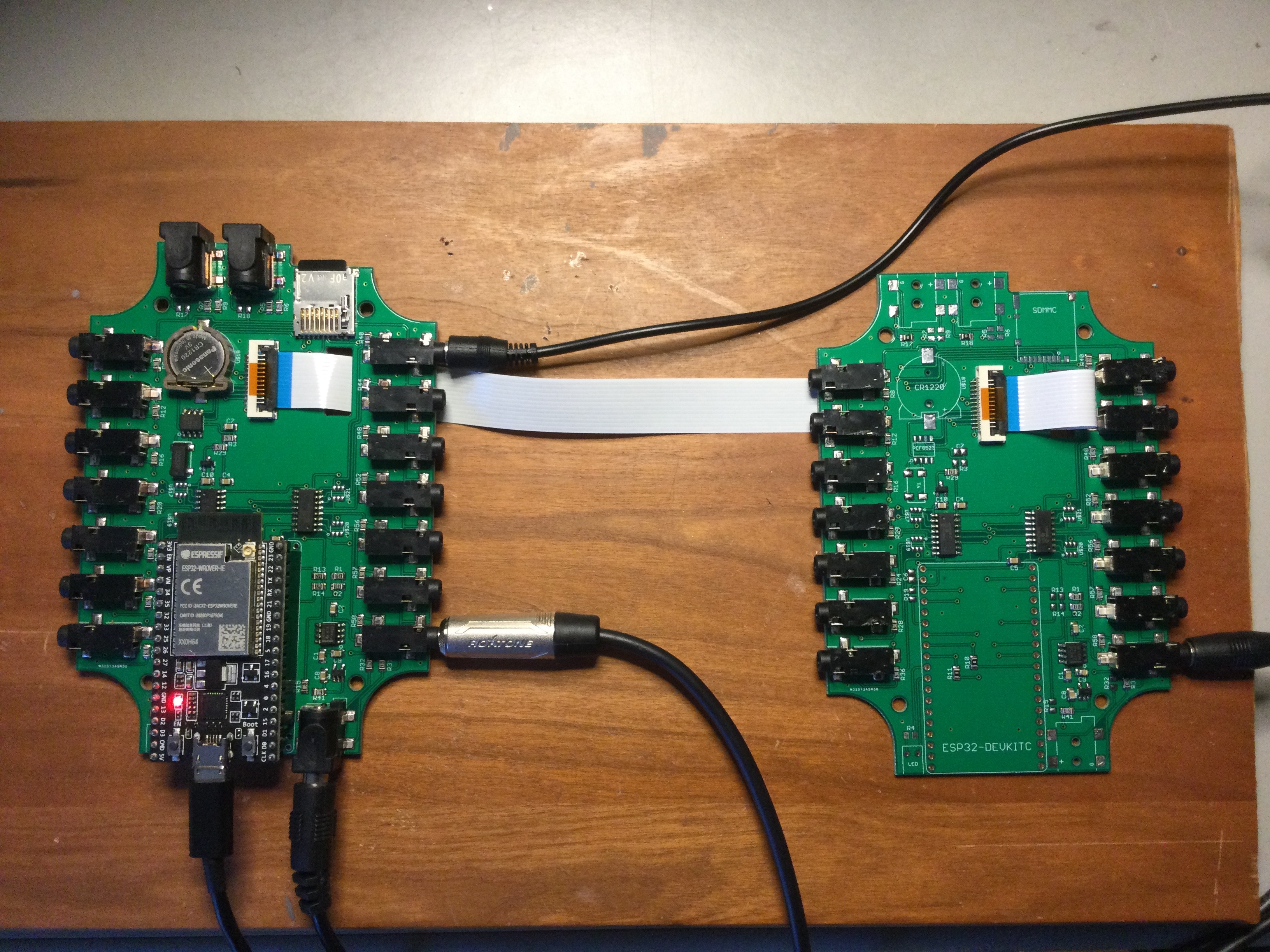
This prototype used headers to allow the ESP32 DEVKIT-C to be plugged in. The production unit will directly solder the DEVkit to the board. This arrangement allows me to swap in different processors. It can currently run with either a WROOM-32 or WROVER ESP32.
Probably not easily noticed is that the SDcard is now a push-push holder instead of the push-pull used on the ESP8266 IoTaWatt. Thjis allows much easier insertion and removal, and also should solve a problem in manufacturing with the old holder.
This board has a separate 3 Volt power supply running off the 5V input to supply lower noise ADC reference and bias. It also affords the ability to change the ADC reference voltage by simply using a different LDO regulator. I’ll be trying out a 1.5V version with 10 Ohm burden in the near future.
The big improvement is the ability to connect an extension board using Flat Flexible Cable (FFC). This cable is not only physically flexible, but also introduces a lot of flexibility in packaging.
As you can see, with the long cable shown, Each of the boards can be packaged in a standard IoTaWatt enclosure and the cables run out and in through a slot in the base.
Another way to do it is to use a short cable and stack the boards:
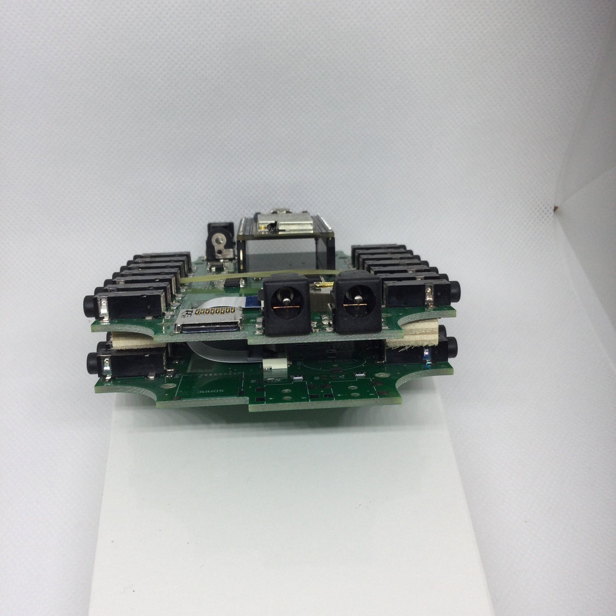
With this approach, a riser could be fabricated to accomodate the extension within the existing enclosure. Either way, by including the inexpensive connector on the base unit, it can now be field upgraded. The connector is a ZIF (zero insertion force) design with a simple locking lever.
This extension board is the same PCB as the main board with fewer components and a few jumper SMT “resistors”. It has it’s own ADC reference power supply so it can be run at a different voltage from the main board. This board will be much cheaper to manufacture not only because it uses fewer parts, but because it doesn’t have thru-hole components.
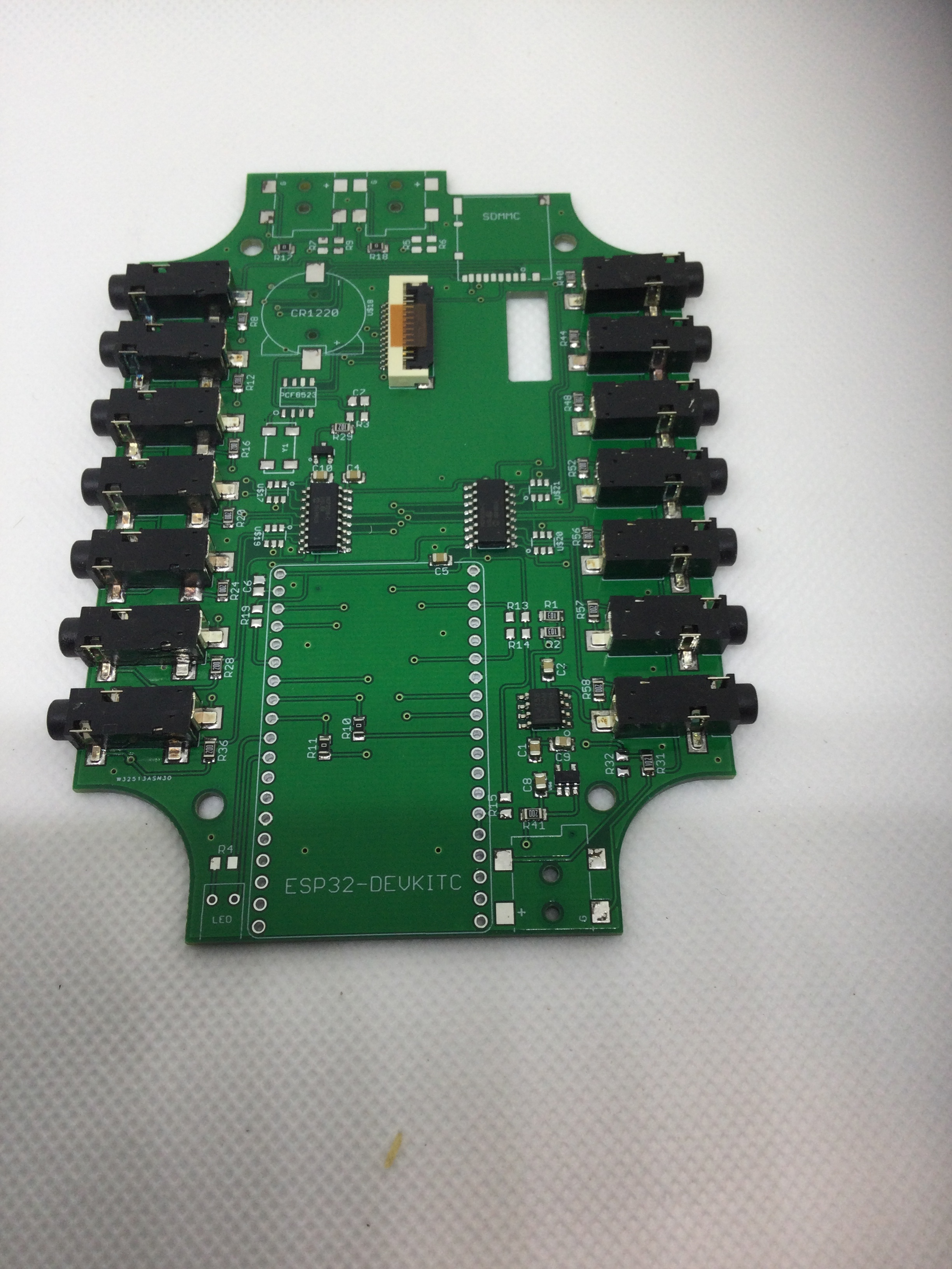
A final version will be a unique PCB and will probably have an I/O expansion chip as well as some circuitry to allow using other sensors. Maybe 10K temperature and/or 4-20mA. There is one MCP3208 ADC port available and one ESP32 ADC port available.
I’ll post another entry to talk about the changes to the firmware and what I hope can be added going forward.
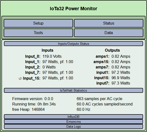
The thing is rock solid. Here’s a preview. Channel 15 is on the extension board.

 that looks amazing, such progress!
