Light commercial 480V/1600Amp questions

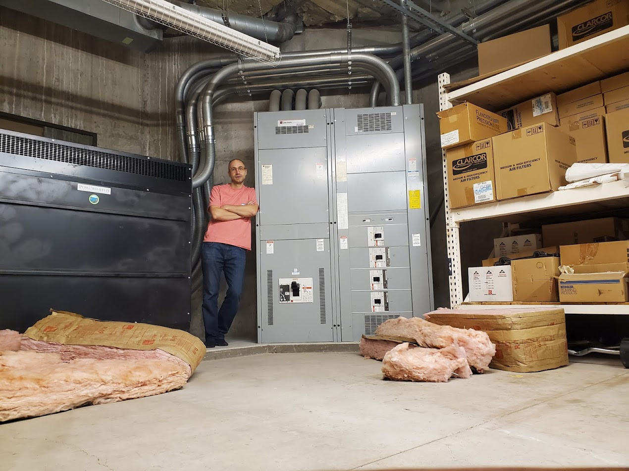
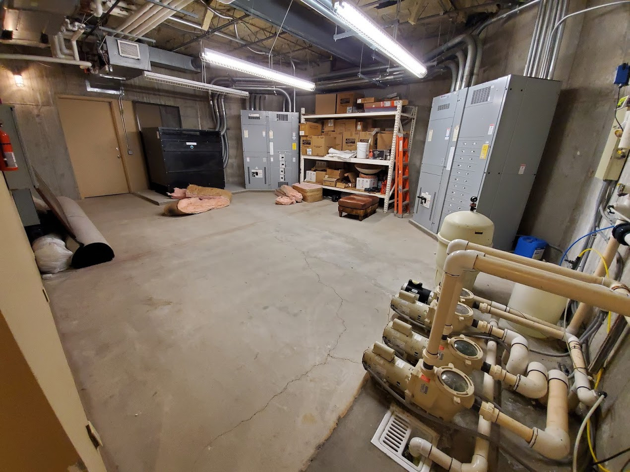
I’m looking into power monitoring for a home built like a light commercial building with 480V 3-phase 1600Amp service and a full-building diesel generator backup. A very large (1600A?) transformer steps down to 208V 3-phase for most of the building. The building is at 8300 feet altitude.

In an ideal world, I’d like to monitor each tier of the system, starting at the service-main and generator inputs, the post-transformer 208V sub-main, then each top-level breaker feeding the building subpanels, then some of the subpanels and some of the important circuits inside those subpanels.

Is this a practical way to approach it? Or should I just focus on doing all the subpanel inputs, high draw circuits, and aggregate to get an approximate building usage?

This brings up several issues.

  1. are there any concerns running at 8300ft/2500m altitude? Most power monitors (honeywell, EKM) are only rated to 2000m altitude. (emporia vue is also technically rated only to 6500ft, but they say they have installations at 8500ft working fine)

  2. is it possible to directly monitor a 480V 3-phase wye 1600amp service main with an iotawatt? (I don’t know if the main is supplied in split cable legs or not, I’ll have my electrician check)

  3. is it practical to measure large transformer loss/efficiency by measuring input and output legs of a transformer? (I can make software changes if necessary)

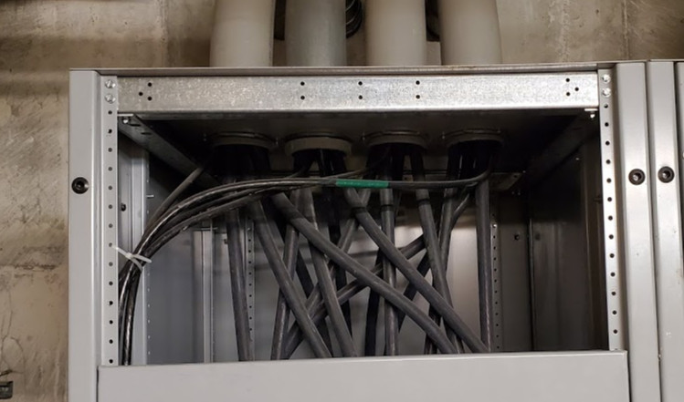
  4. is there a way to mount a remote wifi-antenna? I don’t see any external antenna port on the device pictures. I don’t think running naked CT cables out of a 480V 1600A breaker enclosure is safe or to code, so the iotawatt and it’s reference transformers would be in an enclosure, which would require getting the wifi antenna out of the enclosure for signal. (like emporia vue’s remote antenna)

  5. what are folks doing about cable lengths for CTs and big breaker enclosures? The top level breaker enclosures here are ~8 feet tall by 4 feet wide. I suspect I’m going to need longer than stock CT tables, unless I locate the iotawatt inside the breaker enclosure (for which there is plenty of room, but again this requires a remote wifi antenna). Can I order custom cable lengths for the CTs? Or do I need to rewire them myself?

For reference, here is a picture of the 480V to 208V transformer (on the left) and the 408V main breaker panel on the right.

And here is a wide angle picture of the same room showing the 208V main breaker panel on the right.

From what I can see, there are specific tests to certify equipment at high altitudes, which seems to be defined by the test industry at >2000m. IoTaWatt has not been tested to those standards.

The primary concern seems to be that power supplies might not cool as efficiently in the less dense air.

IoTaWatt uses external power supplies. To the extent you can find a USB power supply and 9V AC transformer that is certified to those altitude standards, you may feel more comfortable, but again, the unit itself has not been tested to those standards.

Yes. Again, like the altitude question, IoTaWatt uses external components (CTs) to monitor current and produces a proportional 0-50mA signal to IoTaWatt. So to the extent you can get CTs to do that, it’s possible. Usually large capacity service is multiple parallel cables. We carry up to 600Ax36mm. Larger are available, but it starts to be custom and expensive. I have sourced 800Ax55mm and they are available.

I have no idea.

No, external antenna not possible. Current 480V install uses ABS box for IoTaWatt. Electricians have no issue with this as it is a low voltage device. Again, the CTs are the only components subject to 480V environment and they are UL tested to higher voltages and the output wires are rated 600V.

Folks usually use standard headphone extensions. It may be difficult to find 600V rated extensions, so yes, you may need to extend yourself.

All this avoids the larger question of what is the real power here? If the 480V 1,600A supply primarily feeds a 208V secondary transformer, then rough estimate is that for the 480V skied to be carrying 1,600A, the 208V side would need to be producing about twice that, or 3,200A. We’re talking about 2MW here. A large commercial install with 480V three-phase using IoTaWatt for the past 20months has just now passed 1MWh. At the running at full capacity your “house” would use that in about a half-hour. So maybe there’s a more practical approach.

That is quite a house. Someone must have a lot of Flux Capacitors that need charging. Or perhaps it is Seven of Nine’s house and she needs all that power for her sleep recharger :wink:

My electrician opened up the 480Y/1600A main panel and it’s fed by four (4) splits of cable, so each set is nominally 480Y/400A.

The cables look to be 1-1.3 inches diameter. It sounds like the 600A/36mm CTs would fit and work. Do you agree?

Here is a picture of the 4-splits of the 480Y/1600A main… The grounds are pulled to the front-left, the neutrals pulled to the back. The ground wires look to be 3/4", the other wires I estimate to be 1"-1.25".

The CT wires are inside a high voltage environment. If they arc or contact something improperly in the main panel, they will be bringing that voltage out into a plastic box.

That said, my electrician was okay with this approach… He wants to put a metal 90 degree sleeve and some conduit on the path out of the main panel to minimize the chance of an arc inside the panel shooting out and catching something else on fire.

And arcs do happen. My 208Y panel has a big metal arc-gash inside from an arc that happened at some point in the past. (reason unknown)

The 480Y->208Y transformer only handles a small fraction of the power usage. Most of the heavy users are directly on the 480Y/1600A service. (Which is why it’s there)

When we did some instantaneous measurements, the post-transformer 208Y main panel total load was 109A/66A/47A… I suspect the 480Y->208Y transformer breaker is probably 250-300A. (I’ll recheck the panel next time i’m down there)

There are five loads directly on the 480Y/1600A service…

  1. a roof-edge ice system (consumes about 40A on each phase of 480Y when running, hopefully less when we update/overhaul the system in the spring, 125A breaker),
  2. 40ton chiller (only runs in the summer)
  3. two elevators (intermittent loads)
  4. radiant heat hydronic fluid pumps (the main pumps run all/most-of the time).
  5. a bunch of fan-coil motors for heating/cooling each zone of the house as needed

My first goal is to get the “whole house” monitoring in 480Y panel, including the 480Y service input, and monitoring of the individual “heavy” 480Y loads.

2 units for 480Y/1600A panel - 3 reference transformers, 12 CTs for the 4-split input, plus 12 CTs for four downstream breakers

1 unit for “heavy load” 480Y Mechanical Panel - 3 reference transformers, 12 CTs for 4 breaker loads (panel input measured in main panel above)


I’m less clear how to handle the 208Y leg of “more typical household loads”.

Originally I was planning to start by monitoring every subpanel breaker in the main 208Y panel, but that’s going to be 4 iota units and 45 CTs to monitor the 15 3-phase breakers, and it still won’t give me any circuit level detail.

An alternative approach is to not put any in the main 208Y panel, and instead start putting them inside the subpanels with the highest usage, so I can get circuit level monitoring of the important loads.

Any advice?

They are 36mm, so easy enough to measure for fit. 4 x 600A is 2,400A. Seems like the 400A would be fine from the numbers you are providing. You will need one IoTaWatt just for the 12 CTs needed for those mains.

I suppose it’s good to be cautious. I believe the insulation is 600V. When I look at some of the “boards” in Australia with 230V/400V my perspective on 480V is a little different.

So that would be roughly 47A/28A/21A on that transformer primary - not a huge load. The rest of the loads you describe, even if they added 100A/phase would still be way less than 200A/phase and <50A per incoming line. So that’s my thinking on using 400A.

Not really. Sounds like you know what you want to do. It probably won’t amount to a lot, but you can measure any three-wire loads with two CTs. Also, 208V two wire loads can be done with one CT. The rule of thumb is that you need one fewer CTs than there are wires.

This is 208Y (wye) with 3 phases and a neutral. So your one-less-CTs than wires suggest I would need 3 CTs to measure 3 phases.

If you’re suggesting I could use 2 CTs even for 3-phase 208Y service, Some of my loads are pretty unbalanced. For example, one panel circuit we measured 13A/7A/1A. How would that be measured with 2 CTs?

I was thinking if we have four breakers leading out of a box, we could get away with measuring 3-phases of input + 3 circuits and derive the fourth 3-phase circuit. (or all of the clamped circuits)

Yes, it’s 208Y, so if you are measuring a four wire appliance, you would need 4-1=3 CTs. But for instance let’s say you have a two wire water heater connected to two of the three phases. That’s what I mean by a 208 appliance. You can measure that with one CT as the current on the two conductors is the same, you only need to derive the composite voltage signal between the two phases and IoTaWatt can do that.

Going a step further, even though you have 208Y and there is a neutral, you don’t need to connect all four to use the three-phase. You could have a three-wire motor, like a pump, connected without using the neutral. In that case, you can measure using two CTs. It’s pretty much the same as the three wires in a standard split-phase system - the unmeasured leg acts like a neutral.

Sure, or you could measure all 4 and get the total by adding them up. Same thing.

I think I understand now. You mean that a single uniform 480Y 3-wire 3-phase load, like a single fan-coil motor or hydronic pump motor can be measured with two CTs.

That may be viable on some of the big 480Y loads. As far as I know all the 208Y service is being used as individual 120V circuits with one wire and the neutral.

That said, we have so many circuits it’s hard for me to think much about monitoring individual loads. Most of what I’m focusing on is top-level breakers that lead to subpanels with a dozen more breakers and loads, not a single uniform load that can be handled this way.

For example, we have 19 top level 3-phase subpanel breakers. That is already 19*3 = 57 CTs / 12 = 5 iotawatt units, plus another iotawatt for the 12 service feed lines, and there are no uniform loads there.

One of the nicest places to use this strategy would be in our 480Y hydronic motors, but I don’t know how I would practically tap them. Each motor relay+breaker is in its own 1-foot-cube metal enclosure, and those enclosures are packed into a 6x3 grid without much mounting space around it. I would have to make custom 8-to-25 foot CT lines to run them to a suitable location for the iotawatts to be mounted. Doable, but I’m currently planning to just monitor the top-level motor-control subpanel breaker, and I’m not sure the whole breaker is so uniform. Maybe it is.

OK, the CT requirements are just FYI, whatever works.

I recommend commodity headphone extensions up to 25’. As a current source, CTs work fine with them as long as you don’t run them close to a source of noise. Running through EMT is usually pretty safe.