If anyone else ends up in the same boat as me with a heap of SCT013 15/30/50 that return a voltage instead of a milliamp reading - then it is a ridiculously easy fix to remove both (the 15amp units only seem to have one) burden resistors and takes no more than 2 to 3 minutes per unit.
Make sure you have a soldering iron with a nice sharp tip and a pair of helpng hands makes everythign go much more easily.
From the bottom push the cable up into the housing a couple of centimeters.
Open the clamp - looking from the top you will see two small blue tabs - this is all that holds the PCB and split magnet unit in the housing
I have found the easiest way is to slide a small jewellers screw driver down between the housing and the PCB and just slightly angle the PCB forward and away from the tabs
If you have pushed enough cable through from the bottom this will provide enough upward force to move the PCB out from under the restraining tabs
SLowly feed more cable in and the unit will come loose from the housing.
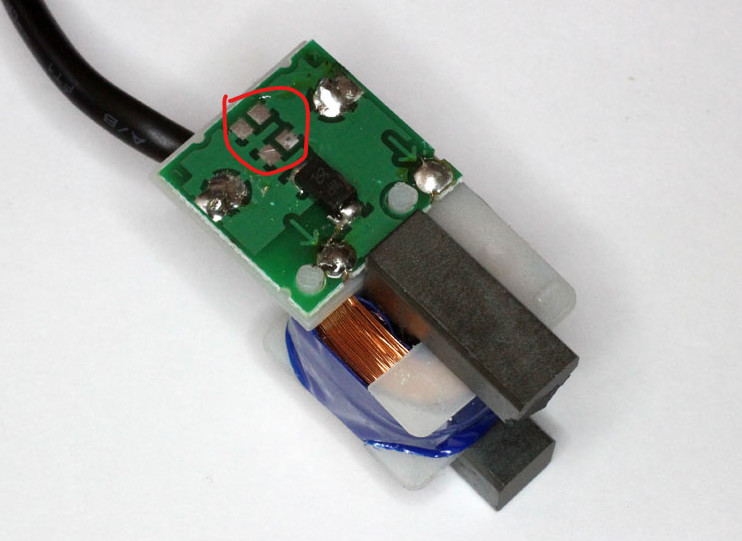
on the PCB you can see the two resistors (they are tiny surface mount units)
Place the PCB in your helping hands clamp and hold the sharp point of your heated soldering iron agains one side of the solder on the SMD resistor and apply a gentle force with the tip of the soldering iron pushing the resistor towards the other side - as the solder melts the resistor will come free of the PCB and bend upwards - you can then push it bakwards and the legs on the remaining side will snap free.
once you have both of these resistors free thats it - slide the unit back together until the PCB is resting under the two restraining tabs again.
Here is a reference for this - this shows a picture of one with the two resistors removed
There is a tiny difference in that for some reason the voltage type current ratio is 1860:1 rather than the 2000:1 of the SCT013-000. So if you configure them (with the burden removed) as an SCT013-000, they will read about 7% higher. Best to configure as generic with 1860 turns and phase about 2.5.
While it’s always good practice to never leave a CT unplugged for any length of time, those protected with a TVS diode can be safely left open for short periods while installing and/or reconfiguring.
These CTs have TVS diodes in addition to the internal burden resistor(s). That’s pretty much belt and suspenders, and @craigcurtin has left the TVS diode in place. It is the black component above where the burden resistor(s) were. These are the same TVS diodes that YHDC uses in their current type SCT013-000.
Just an update on this - got time to get back to it today.
I have modified about 3/4 of my clamps to remove the Burden resistors.
I took a sacrifical extension lead, stripped off the outer sheath to expose the active wire.
Placed 3 diferent CTs on there - all of them the Voltage type from YHDC that i had removed the burden resistor from
I plugged this extension lead into the output of a Watt Meter and a hair dryer into the other end
I initially tried with a 15a, 20a and 30a CT - all of them on the same wire together and into discrete inputs on the IOTAWATT
I set each of them back to having the standard 20ohm burden resistor in the setup screen
Interestingly each of them required a different number of turns specified to return the true voltage that lined up with what the Power Meter was seeing
15a = 1820 phase lead 2.5
20a = 2040 phase lead 2.5
30a = 2390 phase lead 2.5
I tried this on a number of them in each Amp range and once dialed in with the above settings they were all very close to giving the same answers (within 10w or so)
I still have some 50amp ones to do
Let me know if you want any more testing done for your records as i am sure some other idiot (like me) will end up purchasing these as well
As one of the aforementioned idiots, I too managed to order 13 SCT013 of the wrong type (SCT013-060 marked with 70A/1V in my case). I was very happy to find this topic and I just wanted to share my findings after getting rid of several resistors by following your instructions.
After a few tests with an iron and a plug-in heater, I landed on 1880 phase lead 2.5. This seem to be quite spot on compared to my watt meter. (Rarely off by more than 5w). I’ve tested about half of the CTs and they all work well with this setting.
and being a novice, by mistake bought 4 x scT-013-000v that outputs 1v instead of 50mA, i will try removing the resistors.
But i am confused about the terms, Phase, lead and turn values being mentioned, is this something i need add or change in the below generic script for Home assistant ?
ESPHome yaml file i am using is
esphome:
  name: esphome-web-5509cb

esp8266:
  board: d1_mini

# Enable logging
logger:

# Enable Home Assistant API
api:

ota:


wifi:
  ssid: !secret wifi_ssid
  password: !secret wifi_password

  # Enable fallback hotspot (captive portal) in case wifi connection fails
  ap:
    ssid: "Esphome-Web-5509Cb"
    password: "idA0Wqt9m9Hn"

time:
  - platform: homeassistant
    id: homeassistant_time

captive_portal:
substitutions:
  update_time: never
  disp_name: energy-4ch-b1
  ic1Volts: "231.5"

  #.......................................
#...Below script sets up PIN A and B ...
#......then tells CT# to update.........
#.......................................

interval:
  - interval: 15s
    then:
      - script.execute: readCTs
script:
  - id: readCTs
    then:
    # A	B  CT
    # 0	0  1
    # 1	0  3
    # 0	1  2
    # 1	1  4
    # setup for CT1 A=0 B=0 - ct1Amps
      - output.turn_off: pinA
      - output.turn_off: pinB
      - delay: 2s
      - component.update: ct1Amps
      - delay: 500ms
      - component.update: ct1Watts
      - delay: 500ms
    # setup for CT2 A=0 B=1 - ct2Amps
      - output.turn_off: pinA
      - output.turn_on: pinB
      - delay: 2s
      - component.update: ct2Amps
      - delay: 500ms
      - component.update: ct2Watts
      - delay: 500ms
    # setup for CT3 A=1 B=0 - ct3Amps
      - output.turn_on: pinA
      - output.turn_off: pinB
      - delay: 2s
      - component.update: ct3Amps
      - delay: 500ms
      - component.update: ct3Watts
      - delay: 500ms
    # setup for CT4 A=1 B=1 - ct4Amps
      - output.turn_on: pinA
      - output.turn_on: pinB
      - delay: 2s
      - component.update: ct4Amps
      - delay: 500ms
      - component.update: ct4Watts
      - delay: 500ms


switch:
  - platform: restart
    name: "Restart"

output:
  - platform: gpio
    pin: D1
    id: pinB
  - platform: gpio
    pin: D2
    id: pinA

sensor:
  - platform: wifi_signal
    name: "wifi_signal"
    update_interval: 1min
  - platform: uptime
    name: "uptime"
    id: Uptime
    update_interval: 1min

  - platform: adc
    pin: A0
    id: adc_sensor
#    attenuation: 11db #esp32 only


  - platform: ct_clamp
    sensor: adc_sensor
    name: ct1Amps
    id: ct1Amps
    unit_of_measurement: A
    accuracy_decimals: 5
    sample_duration: 200ms
    update_interval: ${update_time}
    filters:
      - calibrate_linear:
          # Measured value of 0 maps to 0A
          - 0 -> 0
          # Known load: 5.706A
          # Raw AC Value in logs: 0.011A
          - 0.011 -> 5.700

  - platform: ct_clamp
    sensor: adc_sensor
    name: ct2Amps
    id: ct2Amps
    unit_of_measurement: A
    accuracy_decimals: 5
    sample_duration: 200ms
    update_interval: ${update_time}
    filters:
      - calibrate_linear:
          # Measured value of 0 maps to 0A
          - 0 -> 0
          # Known load: 5.706A
          # Raw AC Value in logs: 0.011A
          - 0.011 -> 5.700

  - platform: ct_clamp
    sensor: adc_sensor
    name: ct3Amps
    id: ct3Amps
    unit_of_measurement: A
    accuracy_decimals: 5
    sample_duration: 200ms
    update_interval: ${update_time}
    filters:
      - calibrate_linear:
          # Measured value of 0 maps to 0A
          - 0 -> 0
          # Known load: 5.706A
          # Raw AC Value in logs: 0.011A
          - 0.011 -> 5.700

  - platform: ct_clamp
    sensor: adc_sensor
    name: ct4Amps
    id: ct4Amps
    unit_of_measurement: A
    accuracy_decimals: 5
    sample_duration: 200ms
    update_interval: ${update_time}
    filters:
      - calibrate_linear:
          # Measured value of 0 maps to 0A
          - 0 -> 0
          # Known load: 5.706A
          # Raw AC Value in logs: 0.011A
          - 0.011 -> 5.700


#Watts per channel
  - platform: template
    name: ${disp_name} CT1 Watts
    id: ct1Watts
    lambda: return id(ct1Amps).state * ${ic1Volts};
    accuracy_decimals: 0
    unit_of_measurement: W
    icon: "mdi:flash-circle"
    update_interval: ${update_time}
  - platform: template
    name: ${disp_name} CT2 Watts
    id: ct2Watts
    lambda: return id(ct2Amps).state * ${ic1Volts};
    accuracy_decimals: 0
    unit_of_measurement: W
    icon: "mdi:flash-circle"
    update_interval: ${update_time}
  - platform: template
    name: ${disp_name} CT3 Watts
    id: ct3Watts
    lambda: return id(ct3Amps).state * ${ic1Volts};
    accuracy_decimals: 0
    unit_of_measurement: W
    icon: "mdi:flash-circle"
    update_interval: ${update_time}
  - platform: template
    name: ${disp_name} CT4 Watts
    id: ct4Watts
    lambda: return id(ct4Amps).state * ${ic1Volts};
    accuracy_decimals: 0
    unit_of_measurement: W
    icon: "mdi:flash-circle"
    update_interval: ${update_time}


#Total Amps
  - platform: template
    name: ${disp_name} Total Amps
    id: totalAmps
    # Edit below to add all 3 phases for total Amps
    lambda: return id(ct1Amps).state + id(ct2Amps).state + id(ct3Amps).state;
    accuracy_decimals: 2
    unit_of_measurement: A
    icon: "mdi:flash"
    update_interval: 15s
#Total Watts
  - platform: template
    name: ${disp_name} Total Watts
    id: totalWatts
    lambda: return id(totalAmps).state * ${ic1Volts};
    accuracy_decimals: 1
    unit_of_measurement: W
    icon: "mdi:flash-circle"
    update_interval: 15s
#kWh
  - platform: total_daily_energy
    name: ${disp_name} Total kWh
    power_id: totalWatts
    filters:
      - multiply: 0.001
    unit_of_measurement: kWh
Can you share any more info about this voltage spike risk? I’m not sure if all CT clamps have this protection diode… I have some basic electrical knowledge but this stuff is mostly new to me so I’m learning.
If your CT is plugged in, there is very little risk. If you have a very large CT (like one that is used by utility companies on their infrastructure and can easily output 5A or more) the risk is real. A CT is a current source, which means it will do what it needs/can to maintain that current flow. If the resistance increases (say because a wire falls off) the CT will increase the voltage to keep the current flowing. On a big CT this can be deadly.
Mid way down the page talks about this. Note that they are taking about big current transformers. The little ones saturate the core pretty easily and can’t push a lot of power. You still need to be careful, but probably much less likely to be really dangerous.
The TVS diode protection is a good idea to eliminate any issues.
I individually calibrated them - using a known source (in my case a hair dryer) - the number was slightly different for each one (amp rating) - i assume the burden resistor values were slightly different on each unit.
I found that each of them varied with the number of turns depending on the amp rating - so would suggest you do as i have done and strip off an extension lead and use a standard clamp (or a Kill a watt meter etc) to measure the actual power draw and then set your new ones number of turns until you reach a known value)
Its also a good practice to either write the value on the case of each one - or dymo label it to them etc
I compared my meter to a couple of known sources - a hair dryer with a rated output and two different levels and resistive how water service with a 2400w element
It showed me the expected numbers for both of those so i was happy it was accurate enough.
I then took one of the proper CTs (not a butchered one - but one of the accurate units that used to be sold on here) and put it on the same leads