I have a Passive House multifamily apartment building with a 3-phase main panel, each apartment has a 100A sub panel. There is a single meter on the building and tenants are not charged for electricity.
My goal is to roughly monitor daily energy consumption at the apartment level so I can understand variation across apartment units and how that evolves seasonally. I am not monitoring at the circuit level within units. I do not need billing-level data accuracy. If there is a systematic error in my data, that is okay as long as the relative error is the same across apartments.
My electrician installed the hardware based on intuition, and I think he did it as though it is a single phase system. When I went to set up the software I discovered the 3-phase instructions. He is now unwilling to help me with this further.
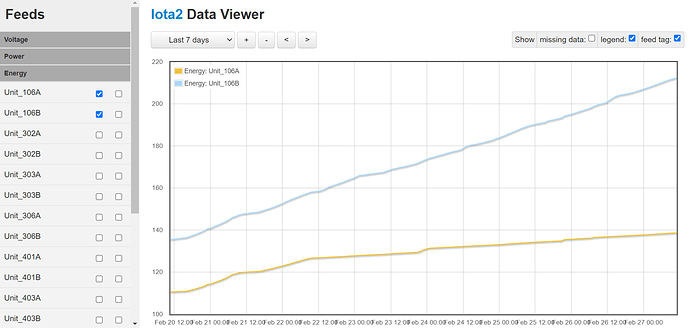
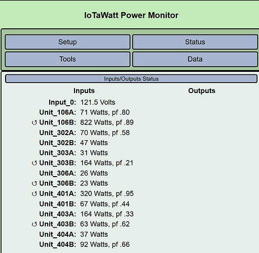
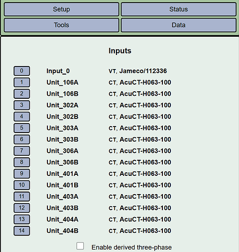
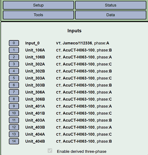
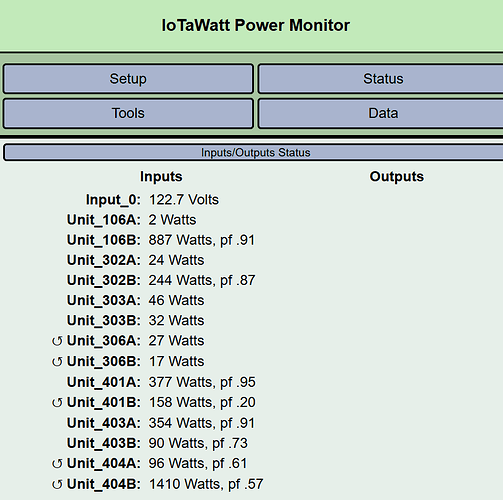
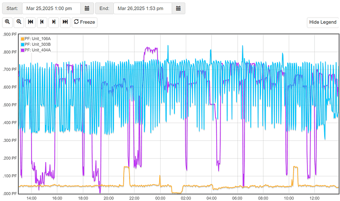
These are images of the input set-up and an example energy chart.
My electrician is insisting that the system will gather the data I need as he’s installed it currently, and that we don’t need to go the extra step to set up the derived references.
For example, he thinks that “Unit106_A” watts + “Unit106_B” watts = total kw consumed by the apartment.
He is unwilling to draw a line diagram or provide a photo of the main service. Based on my conversation with him, its also clear that he didn’t realize the CTs needed to be installed in a specific direction aligning the arrow on the CT with the flow of the electricity.
My questions are:
- Can the current set up (1 CT per subpanel wire, for a total of 2 CTs per sub panel) provide “good enough” data for my use-case?
- Is he correct that I can just add the wattage data collected by the 2 CTs and that is how I arrive at a total consumption for a given sub-panel?
- Do I need to flip any of the CTs / can that be confirmed by looking at the data they are collecting rather than by visibly inspecting the CT install?
IotaWatt works fine with three-phase, you just have to set it up so that it can do the phase shifting needed. Please post:
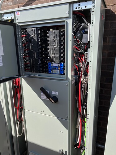
- A high resolution, well lit, picture of the panel with the cover off showing the CTs.
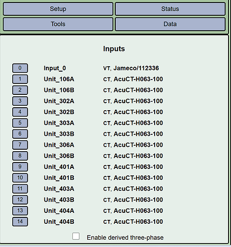
- A screenshot of the inputs setup menu.
- Something relating the breakers (they are usually numbered) to each IoTaWatt input.
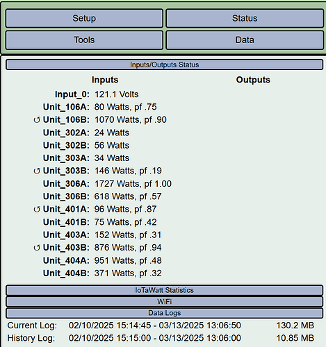
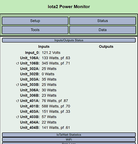
- Another screen shot of the status display.
Answers to questions:
- Yes, but only if properly configued for three phase.
- No, one will be correct and the other will be about half of the proper value
- Some may need to be reversed, but that can be done in the app rather than physically reversing them.
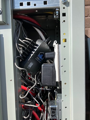
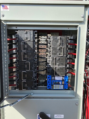
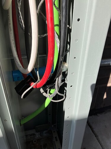
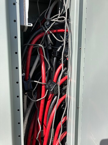
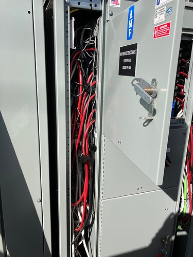
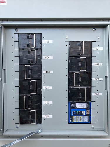
Included here are photos of one of the two panels that are wired with a base unit and sensors. There is very little space in the electrical service, so I given how tightly everything is packed I don’t know that you can glean much from the CT photos.
Included are screenshots of the inputs setup menu and status display.
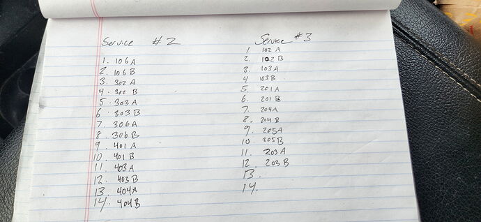
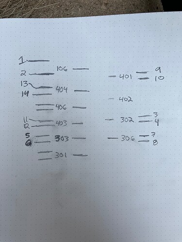
Lastly, there is a picture of the list provided by my electrician of which breakers aligned to each IotaWatt input. I have 2 base units set up on 2 different panels. I only configured one of the units before I realized it wasn’t set up for 3 phase, so I only have one setup and one status picture to share.
Cody
I see the list, but I don’t see any way to connect his breaker name to the physical breakers. For instance I need to know which breaker and which wire (red or black) 106A is.
There is a label panel, which is off in the photo, but even if I take a photo with it back on, the set up and lack of space in the box will make it impossible for you to see in a photo which wire (black or red) 106A vs 106B is.
If the next step is identifying that - I can do so. I will build a data table that has the following fields/columns: Label, Wire Color, CT unit #, channel/port #.
If I collect and provide all that information, can you provide me the next steps after that?
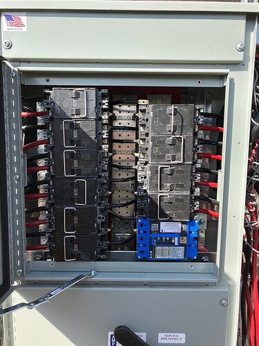
Not real clear on whether that will be unambiguous. If you take the panel picture above:
Going down the left side there are 12 cables. From the top:
1. Black   L
2. Red     C
3. Black   R
4. Red     L
5. Black   C
6. Red     R
7. Black   L
8. Red     C
9. Black   R
10. Red    L
11. Black  C
12. Red    R
On the right there are 8 pairs. From the top:
1. Black C
2. Red   R
3. Black L
4. Red   C
5. Black R
6. Red   L
7. Black C
8. Red   R
I’ve appended the buss that each appears to be connected to (Left, Center, Right) If you could add the name and IoTaWatt input number for each, I can work with that.
The box has three busses. One down the center that you can see, and one on each side under the pull-fuses with jumpers across the center. This determines which phase each wire is connected to.
With that information I can begin to solve the puzzle, but it may take a couple of passes to get it all right.
I’m guessing that 106B, 306A, 401A and 403B are on the same buss.
Included here are photos of the panel labels and a diagram showing which busses. There are no CTs on any of the center busses.
Following this convention (Iota Input Port #, Given Name on Input Screen, Cable Color, Left/Right/Center) you get the following.
- 106 A - R - L
- 106 B - B - L
- 302 A - R - R
- 302 B - B - R
- 303 A - R - R
- 303 B - B - R
- 306 A - R - L
- 306 B - B - L
- 401 A - R - L
- 401 B - B - L
- 403 A - R - R
- 403 B - B - R
- 404 A - R - R
- 404 B - B - R
The wire colors and phase designations appear to be all wrong. For instance there are no C (Center) phase designations, only R and L and as I see it input 2, 106B is Red and phase C.
Identifying the pull boxes is a help, but given that you have the cable colors reversed, can you please double check your work.
Yes-you are right, I flipped all the colors, the list below is corrected.
- 106 A - B - Left
- 106 B - R - Left
- 302 A - B - Right
- 302 B - R - Right
- 303 A - B - Right
- 303 B - R - Right
- 306 A - B - Left
- 306 B - R - Left
- 401 A - B - Left
- 401 B - R - Left
- 403 A - B - Right
- 403 B - R - Right
- 404 A - B - Right
- 404 B - R - Right
Try this:
Check “Enable derived three-phase” in the inputs setup menu.
All of the inputs should now show “phase A”.
Edit each of the following inputs to change the phase assignment as specified.
 1. 106A   phase B
 3. 302A   phase C
 4. 302B   phase B
 5. 303A   phase C
 6. 303B   phase B
 8. 306B   phase C
10. 401B   phase C
11. 403A   phase B
13. 404A   phase C
14. 404B   phase B
Then post a screenshot of the status display. There are two solutions with the data available. This was one of them. I should be able to tell if its correct looking at the status display. If its not, I’ll post the other solution which is swapping phases B and C.
It appears I was correct here as they all are on the same phase A.
Thanks for working with me on this!
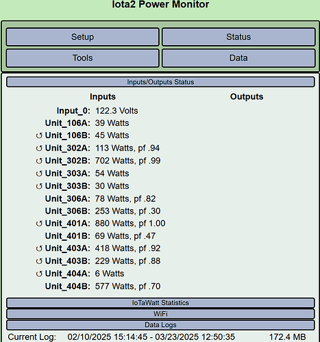
Screenshots of setup and status screens:
The good news is that it appears the coin-toss was correct and the phase assignments appear mostly good.
The bad news is that there are still a couple of inputs that appear to be incorrect. Specifically 306B and 401B. 306A and 401A are almost certainly correct. That leads me to suspect that what is plugged into inputs 7 and 9 are not the black wires from 306B and 401B. You might want to locate those CTs and trace the wires back to the IoTaWatt inputs.
There are also some others that I cannot be sure of because they are using very little power in the status display. A few more status screenshots might help sort that out.
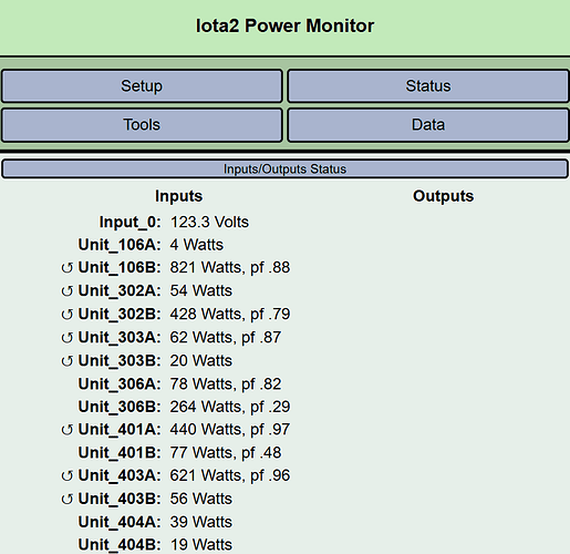
Here are a couple more screen shots. I will retrace/check my work on the wires in the next day or two. Thank you again!
That reinforces the problem with 306B and 401B.
There is insufficient usage on 106A, 303B and 404A to verify. Can you plot PF for those for 24 the last 24 hours and include the statistics tab in the posting? Please use Graph+ instead of the Original Graph.
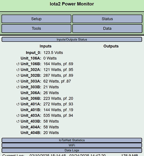
Lets get rid of the “reverse” symbols on the correct phases by going to the setup for Input_0 (VT) and checking “reverse”.
At this point you can create outputs that add the A and B values for each of the units.
I have now checked reverse for Input_0(VT).
Below is a status image after making that change.
Also below is the plotted PF as requested. Please note that this data does not reflect the change to the reverse setting above.
I retraced channels, CTs, wire color…
Port 8 = 306B = Red Wire on Right Side
Port 10 = 401B = Red Wire on Right Side
Port 7 = 306A = Black Wire on Right Side
Port 9 = 401A = Black Wire on Right Side
Notwithstanding that you traced the wires, I’m still not comfortable with 306B and 401B and also 106A is possibly incorrect. Nevertheless, you say you verified that the CTs are as configured. I can’t physically verify this info, I guess you can just go with it.
Thanks for all your help!
