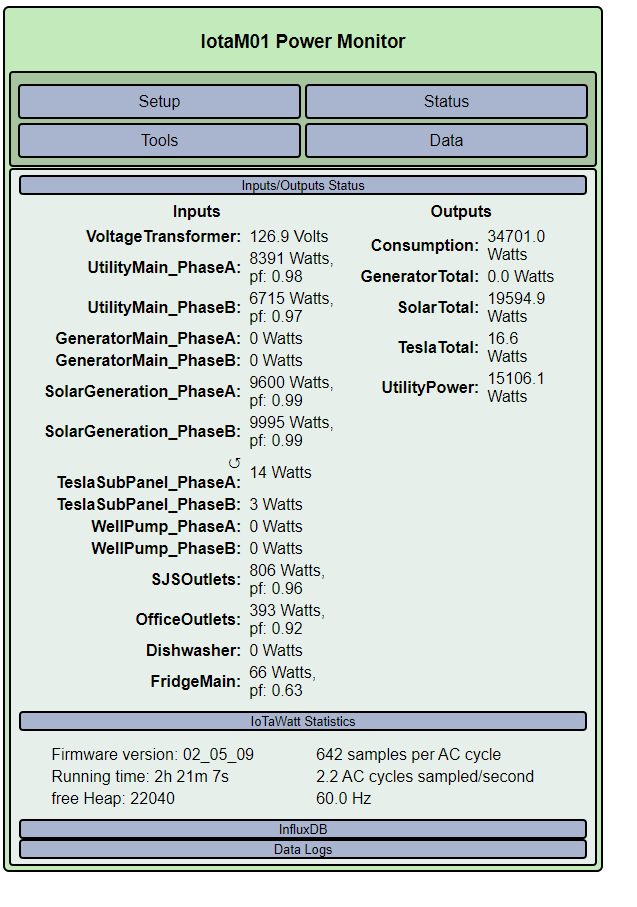
I’m not seeing a negative input except the TeslaSubPanel_PhaseA.
I do see other issues that may need attention:
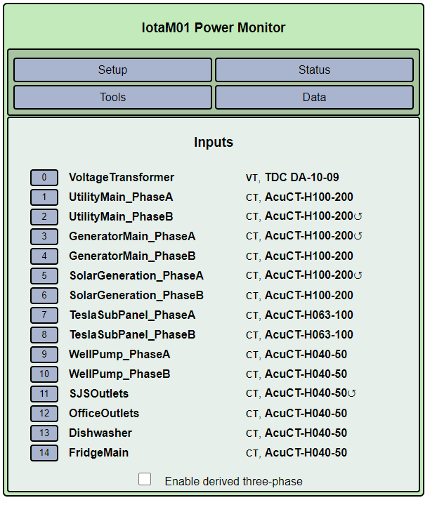
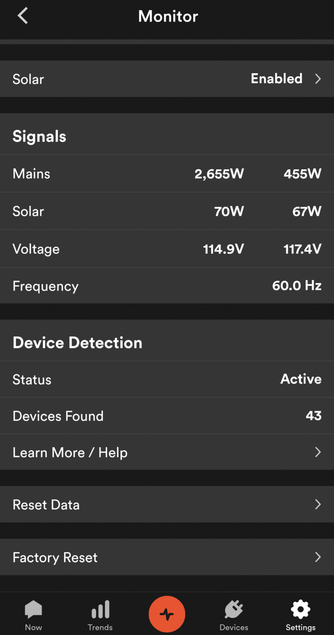
You seem to have CTs on both legs of the solar inverter output. Most inverters are two-wire and output the same on both legs. The IoTaWatt is reporting significantly different power on the two legs, which should not be the case. I believe the Sense only uses one CT for the solar. Is that true in your case?
A 20,000Watt solar array would put out more than 80Amps on each leg. I’m wondering how that is fed into your system. There are two different approaches:
Type 2 as it is commonly referred to, brings the inverter power into your panel through a circuit breaker at the bottom (opposite end from the mains). In your case that would probably be a 100A breaker or greater.
Type 1, as commonly referred, brings the inverter power through a breaker in a separate enclosure and connects the output to your mains before (upstream) from the mains.
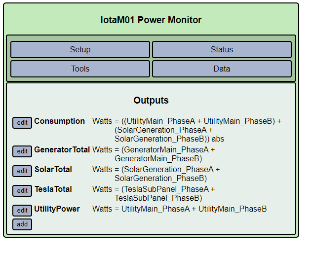
With type 2, the inverter output reduces the mains load and drives the mains negative when the inverter outputs more power than you are using. Consumption is the algebraic sum of the mains and solar.
With type 1, the inverter output has no effect on the mains power reading, which is your consumption.
From this data, I believe you have type 2.
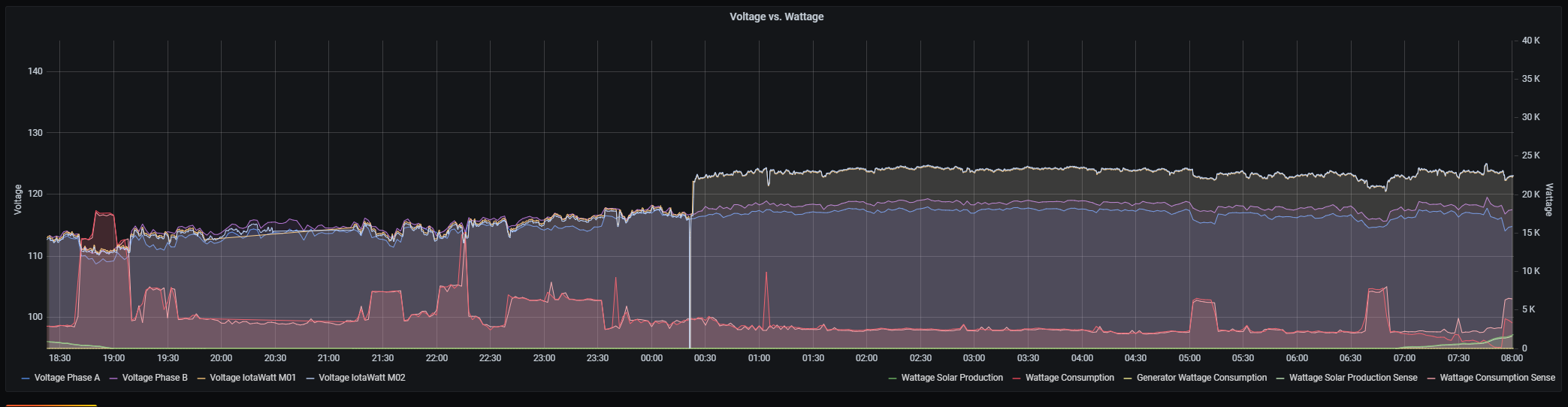
Moving on from that, I think the Sense and IoTaWatt agree within 1% of the Mains power.
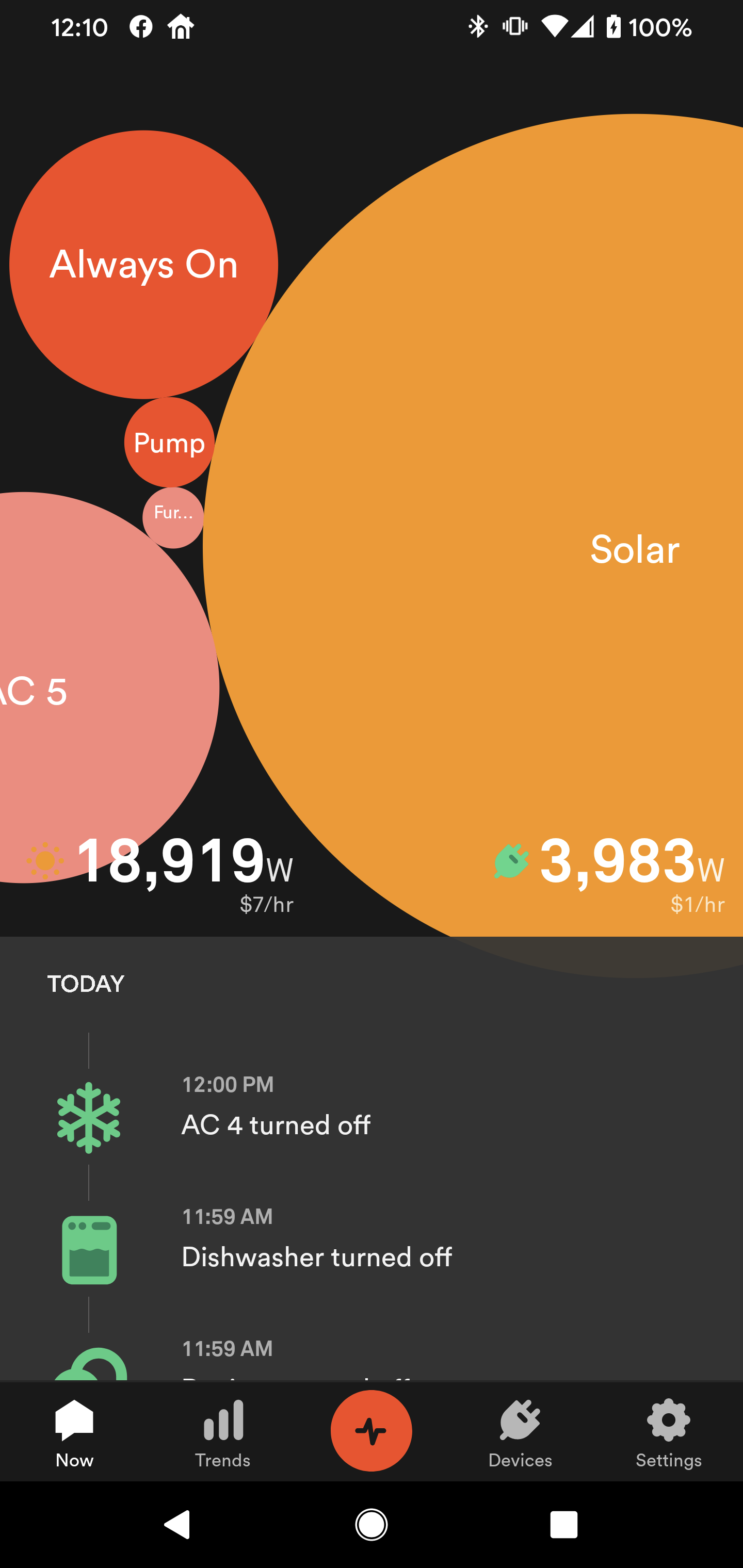
I think the 3,983 that Sense is reporting is computed by adding a negative mains power of 14,936Watts to the positive Inverter output of 18,919Watts.
The IoTaWatt reports a similar number for the mains at 15,106, although it’s positive. I suggest that you should check “reverse” for UtilityMain_PhaseA and uncheck "reverse for UtilityMain_PhaseB. Then the mains should show negative and your Consumption output should be closer to the Sense.
If your inverter is truly two-wire, i.e. it has no third neutral conductor, then you should use just one CT and check the “double” box. But before you do that, could you move the CT that’s on phaseB to phase A and see if the two read differently while solar is producing. If they are different, could you try moving one of the Tesla CTs to the same wire and see how it agrees with the other two? There is something wrong here and this experiment might shed some light on it.
I don’t think the IoTaWatt and Sense will ever 100% agree on instantaneous readings for a variety of reasons:
-
Solar fluctuates considerably and getting simultaneous screenshots is difficult.
-
IoTaWatt damps the status display so it is not an exact measure at any point in time.
-
Sense probably damps as well and there could also be a latency between the upload to the cloud and query by the app.
-
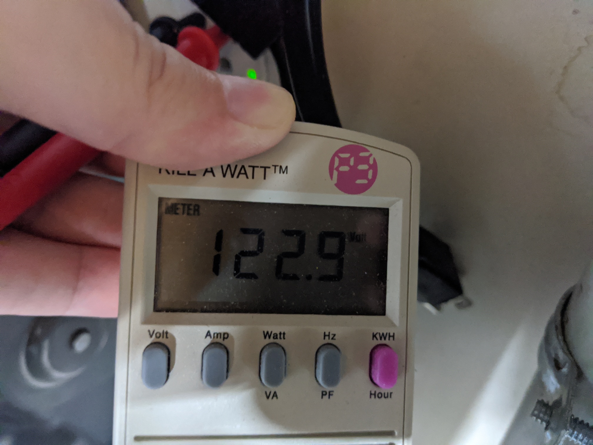
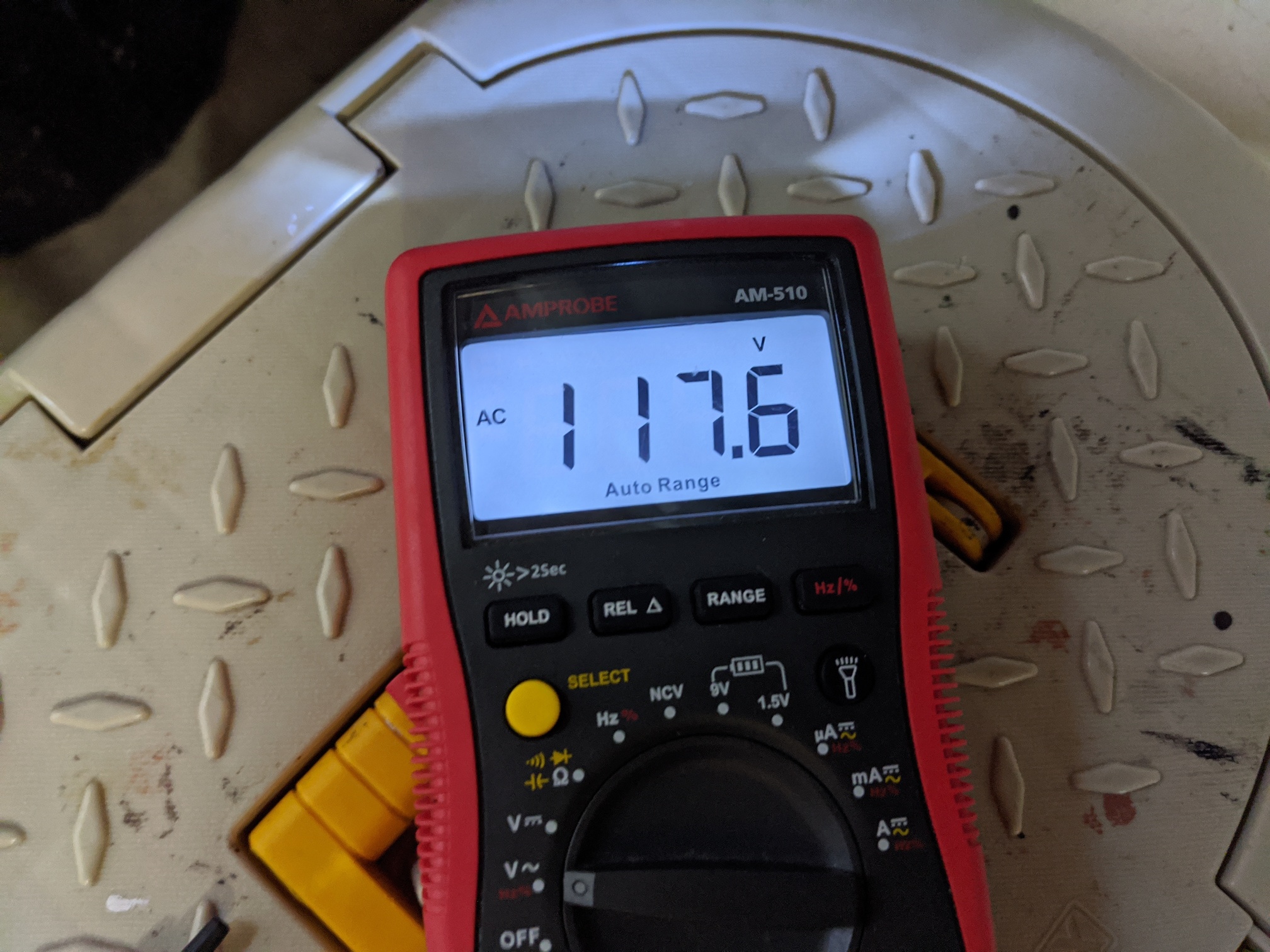
IoTaWatt, as configured with a 120V AC adapter, is subject to error from voltage swings between the two phases caused by load and the resistance of your neutral cable. (That can be eliminated by using a 240V VT). Sense may be using the 240V measurement, or may be using one of the 120V measurements.
These problems make the instantaneous reading hard to compare, but the energy readings should be very accurate, at least with IoTaWatt. You can track the IoTaWatt kWh over a couple of days vs the meter. You can also track the IoTaWatt solar generation kWh against the inverter display. The same should be possible with the Sense and will show best where these errors lie.
UPDATE: Original post had Type-1 and Type-2 solar incorrectly labelled. This has been corrected. Note also that the post had assumed the wrong type and that is still the case. Subsequent explanation by @RedTechie has clarified the type.