Hi all,
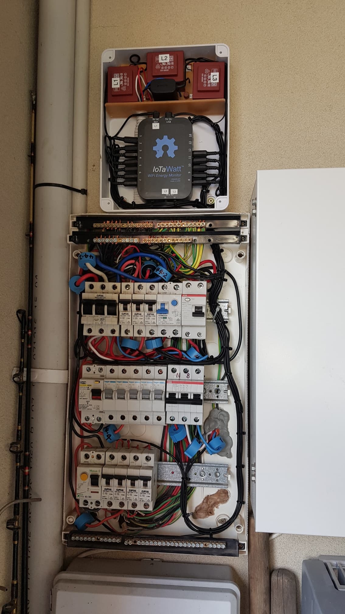
Just finished installing.
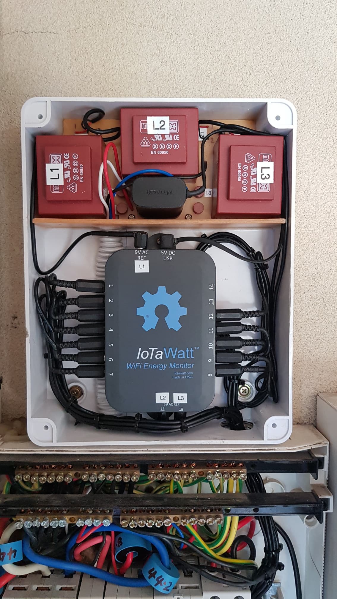
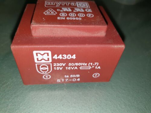
Wanted to keep it compact so had a gamble and purchased 3 Myrra 16Va 230 to 15vac PCB transformers, they came very cheap from fleabay. Quite heavy little suckers.
Had some 10k resistors lying around and used them in series to drop down the 18.8vac open circuit voltage.
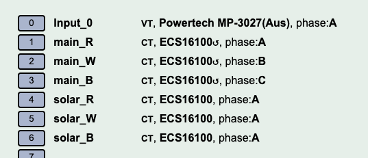
All the CT’s are HWCT-004, being 3 phase will never get anywhere near 50amps with mains.
Purchased just the bare CT’s and soldered wire and plug with TCV diode.
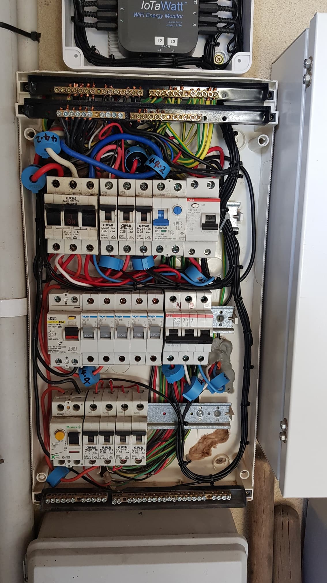
Calibrated the transformers phase shift as compare to the known CT’s phase shift(+0.35) using the browser url: iotawatt.local/command?vtphase=11 to obtain a measure of the relative phase difference between CT11 and VT0. Had a pure resistive load of 2400 watts kettle on circuit CT11 with PF reading 1.00. Sampled many times with an average value of -0.48, was very surprised that is was so low!!
Subtract the resulting phase difference from the phase correction of the CT (+0.35) to get the phase shift of the VT, ie 0.35 - (-0.48) = +0.83 deg phase shift for the transformers.
Hope I did the above correctly as the phase shift seems very low for these transformers.
Finished of with Voltage Calibration of the VT’s with fluke that measures rms.
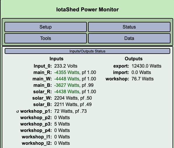
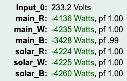
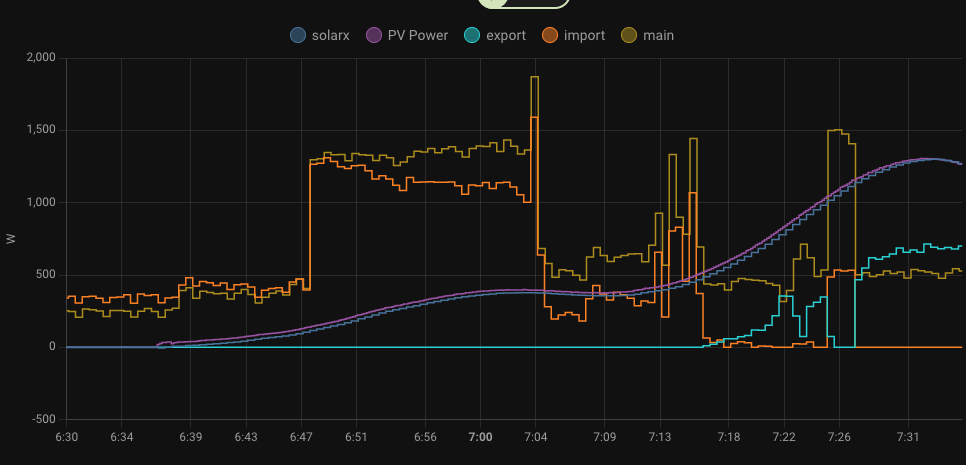
Seems to work great. Uploaded data to PVOutput.
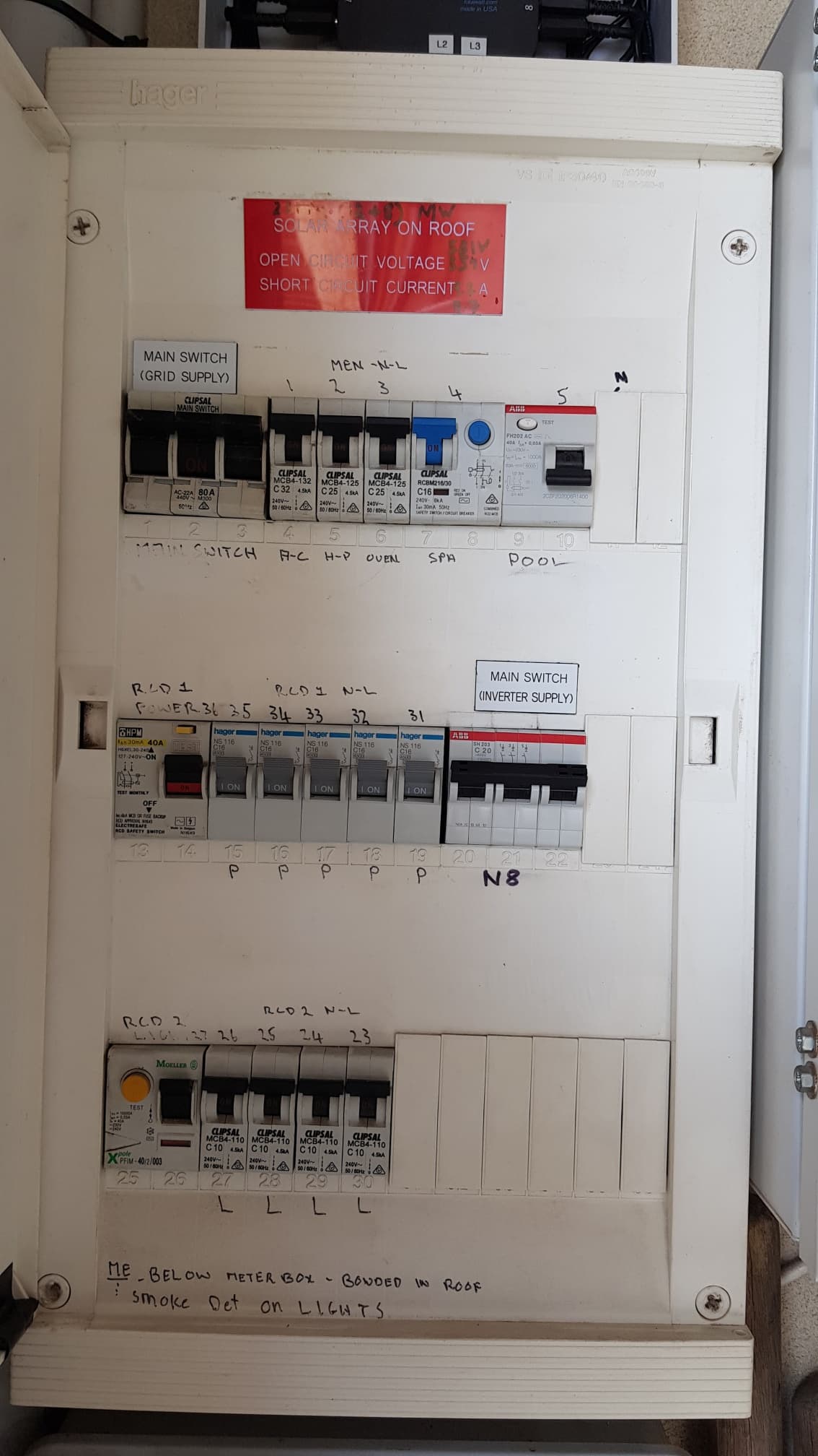
Not sure if I got the correct consumption configured output for PVOutput. I have solar (3phase inverter) with feed back to grid.
(main1+main2+main3) + (solar1+solar2+solar3) correct?
The docs page shows “max 0” at the end?? what is this for?
Good job on the install! I’m in AU too (Melbourne).
The basic install on my own house panel worked perfectly first time. The numbers look good. That’s a single-phase sub-panel off the main board which is on my shed.
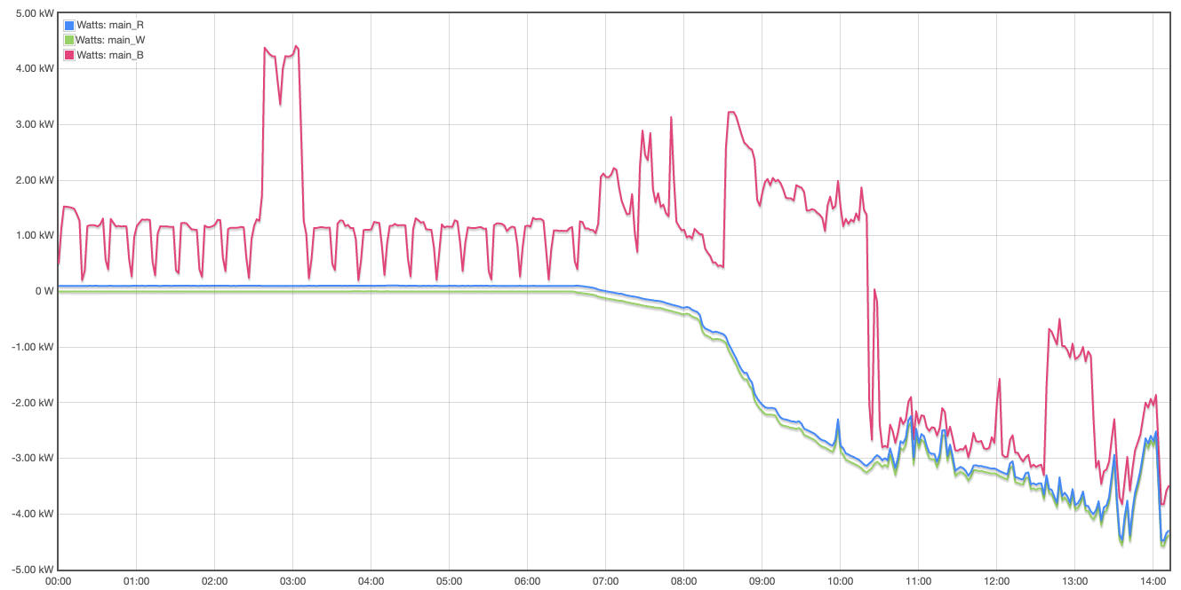
But (with a second iotawatt) I can’t for the life of me figure out how to configure my 3 phase + solar connection. I have each of the three mains side clamped, and each of the 3 lines from the (3ph) solar inverter, as well as each of the circuits. None of the 3ph numbers seem to make sense, they flip flop around, and make my brain hurt. I think I’m missing something.
Figured it out (for main import/export). Follow instructions properly.
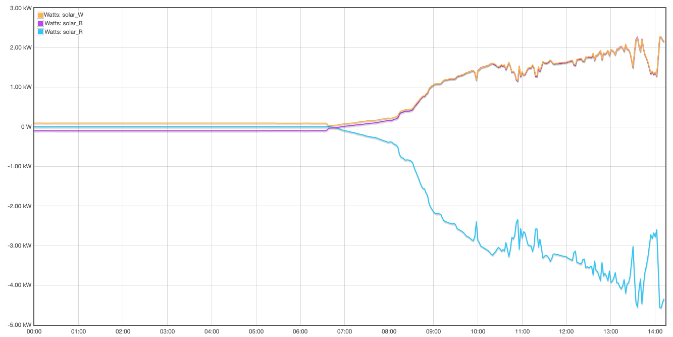
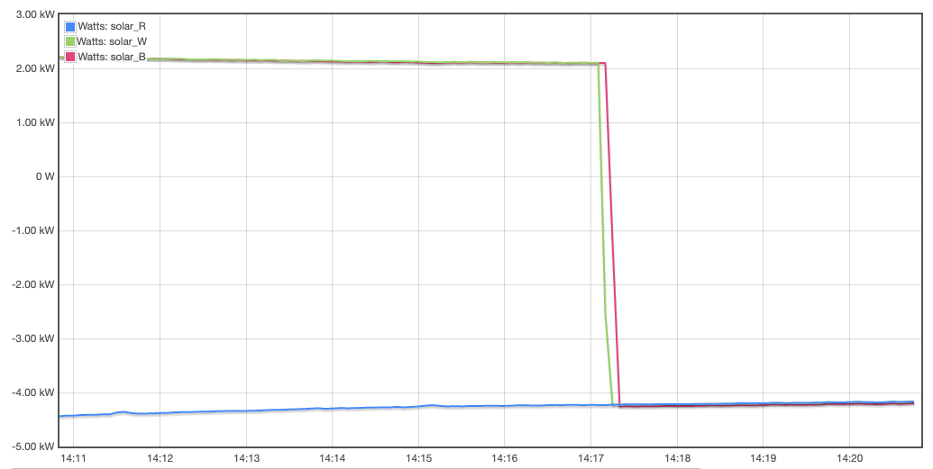
The solar numbers still don’t make any sense, but maybe they’re clamped in wrong place. The solar fuse/breaker is pretty much directly wired to the main circuit, so it’s not measuring just what’s coming from the inverter.
The CTs and wiring are behind a panel now. From what I recall, the R/W/B lines from the solar go to a three-pole breaker, and from the other side of them go directly to the R/W/B of the main/grid circuit.
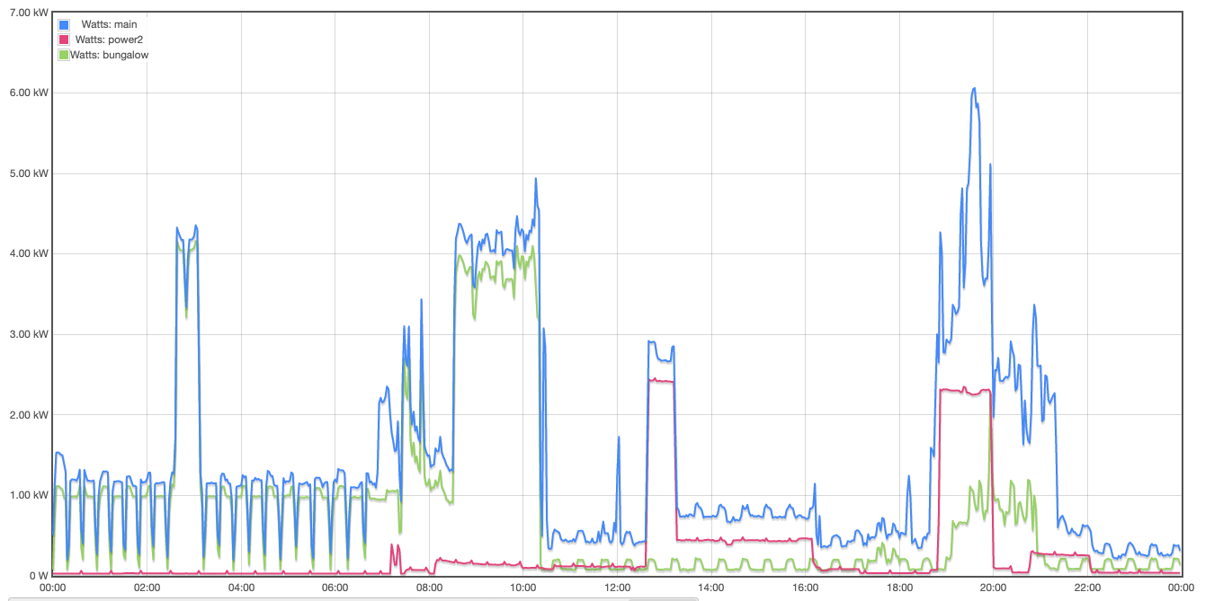
Are you talking about the many peaks, or what looks like your drier running at 4kw?
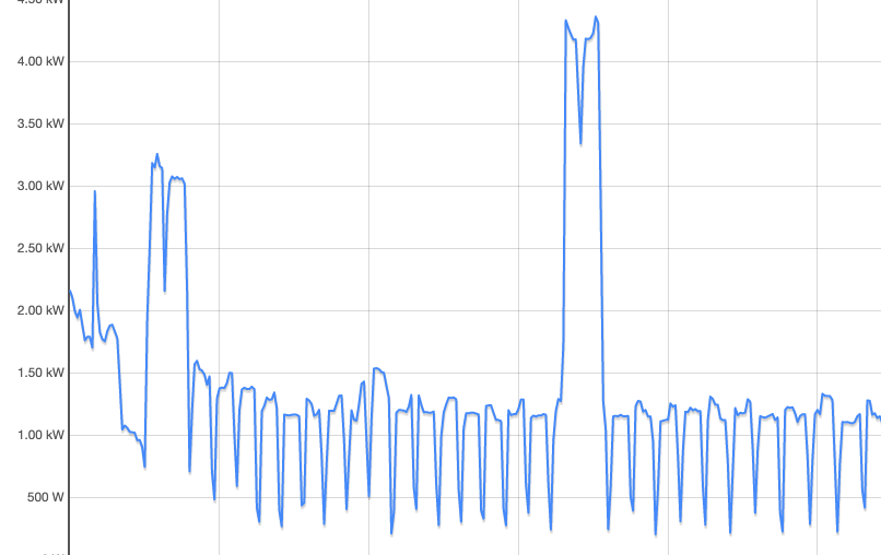
Regarding the many cyclic peaks, my car charger does that. I believe it stops charging for a bit and lets the battery float to check on the state of charge. I assume it is getting the open circuit voltage.
I’m talking about the extremely repetitive drop/peak exactly every 30 minutes. I mostly see it on the “bungalow” circuit (which includes a hot water cylinder, and some lights/heaters which are probably off); but also see a smaller version on power2, which is half the circuits in the other building. Just wondering… not a problem as such.
Looks legit to me. You would need to track it down in the bungalow panel. Happens regular enough that you should be able to switch breakers off and tell within a short time if that’s it.