New Installation - Australia, Regional NSW

What is the draw? Some devices have a low watt draw always. My furnace uses about 7W when it is doing nothing. My Heat Pump Water Heater uses about 2W doing nothing.

This is some of the interesting data Iotawatt can help you see.

That might be because the current in the two wires cancel each other out. You HAVE to put multiple wires in the correct direction. If you only have one wire, Iotawatt is usually smart enough to figure out it is backwards.

Thanks

~150 W
Makes zero sense. Here’s an example of the power trace showing when I had the stove on for a handful of minutes this evening:

Can see either side of that the weird idle power draw. I would notice this sort of draw in the billing meter.

My ducted AC does have an idle power draw which can be of this magnitude at times (might be running the fan without cooling), but that is already being captured with its own CT:

Wires are definitely in the same direction, they share a sheath as they exit the main circuit board en route to the mancave. All same phase.

I have a CT on each individual wire now (there are 3) but the power numbers are not correct. So something is up.

I have the exact same set up for my other outbuilding and it is reporting power correctly as far as I can tell (e.g. I can see the fridge cycling on/off), while for the mancave I don’t see that. I know the fridge cycling is happening as I have a separate power monitor for it.

I need to do more investigating. It’s a complex board.

But now I have another problem, the Home Assistant integration appears to already be broken:

Screen Shot 2023-03-22 at 7.29.29 pm

Looking at the documentation for known problems it appears there is no clear fix for this.

Which is a complete bummer as the Home Assistant integration is absolutely key to me making use of this system.

From your plot it appears the CT is working as it shows the incremental load of the stove. I would suggest that either the stove has a constant load that you are not aware of (150W should be producing some heat somewhere), or there is another load on the circuit. In either case, try unplugging the stove and see what happens. If the 150 Watts goes away, it’s in the stove. If not, it’s another load on the circuit. Try turning off the breaker and see if the 150 Watts goes away and what else goes off.

That usually happens when you put the CT around both the hot and neutral. The current is going one way in the hot and the opposite way in the neutral, so they cancel each other out.

You must have discovered by now that it only takes a few seconds to show up on the status display, and at most the interval for the period that you selected with Graph+.

Home Assistant is user contributed, so you might go to their forum for more information. Don’t know if its related but the HASS folks will not accept a PR for IoTaWatt because it violates a rule that cannot be reasonably satisfied by IoTaWatt. It attempts to avoid an infrequent, minor and easily explainable effect of output name change by imposing a requirement to modify IoTaWatt such that it could cause significant, obscure and befuddling consequences.

Picture?
Wires in the same sheath are typically either:

  1. Same phase - line (black) and neutral (neutral) and ground (bare/green/green-yellow) But, the IEC color code is different and that is probably what is in use there. Brown is line (Brown will take you down). Blue is neutral. Green-yellow is ground if I recall correctly.
  2. Different phase - line (black), line (red), ground and possibly neutral. In the US it is legal to use the white wire in an NM cable for line as long as it is marked appropriately.

So, yeah you either need to only use one wire or you need to reverse one of them, depending on what the wires are actually hooked up to at the panel. Pictures make it much clearer.

Thanks for responding. I appreciate it.

Yeah, there is definitely no heat. This is a benchtop 4 hob induction stove. Indeed without a suitable pot or pan on a hob the unit cannot operate. It will switch itself off.

I have tried that. There is the double pole breaker in the main circuit board (oven and stove), and the mandatory wall switch in the kitchen for turning off the power supply to the oven and the stove. The oven and the stove are each on a different phase. Switching either off sees power hit zero while nothing else loses power.

The CT is around the single wire feeding the induction stove but I need to do more investigating. Despite a reorganisation, my board is a complex mess so unravelling what’s going on is going to take time.

I guess it’s possible, I’m not ruling anything out and I need to keep experimenting.

Pretty sure I’m not dealing with a neutral though. All the neutrals in my cabling are black so I will trace that back to the main neutral link to make sure.

In an effort to rule out such effects I placed a CT on each individual wire, and the numbers from the individual wires make little sense either. I was hoping to cover all three wires with one CT, and then just one of them which supplies the aircon circuit.

Again I need to keep experimenting to work it out. I will also visit the outbuilding sub board to see what colours the wires are down there.

But glad for the thoughts and suggestions in as it can help to validate stuff or makes me think of something else to try.

Has not been my experience. I found it can take minutes to show up in the status display, which is why I was getting confused as I was expecting a faster response.

Initially I though the CT was at fault or I was clamping the wrong wire or some other user error but I discovered by accident that the data would appear if I waited long enough. It was the same each time I added a CT.

Indeed because of this delay whenever I added a new CT I got into the habit of doing something else in the interim and to check in later to see if it had started to show up in the status display.

Yeah, thanks. I had a poke around some related threads and it seems this is not an unusual problem. It would also seem no one is interested in resolving it, certainly no clear solutions are posted. I wish I had known about it before as somehow I allowed myself to think it worked just fine.

I will find what appears to be the most relevant thread and start a conversation there. It’s mighty disappointing as I had thought the HA integration was seamless and without a working/stable HA integration the IotaWatt has little value to me as I planned to do some load management with HA automations.

I’m sure there’s some sort of workaround. If / when I find a way, I will post my experience.

I’m not a programmer nor a comms guy so understand little of the technical stuff. All I know is it is broken. I even removed the integration to reinstall it and it flat out refuses to re-install.

What I take from this is that you are not allowed any input into the HA integration, which is, frankly, a bit strange on their behalf.

Thanks for your assistance, I will keep trying!

Thanks for responding.

Your initial thoughts are along the right path.

But my set up is not quite normal. So brace yourself, this will be long…

The normal bit:

Our wire colours are different to the US, and they have changed over time. My home is old enough (50 years) to have a mix but mostly follows the typical colour codes used here for last few decades:

Single phase circuits it’s:
green/yellow or bare wire = earth
black = neutral
red = active

3-phase it’s:
yellow/green = earth
black = neutral
red, white, blue = active

While the two phase supply (to oven and induction stove) uses the red and white as actives.

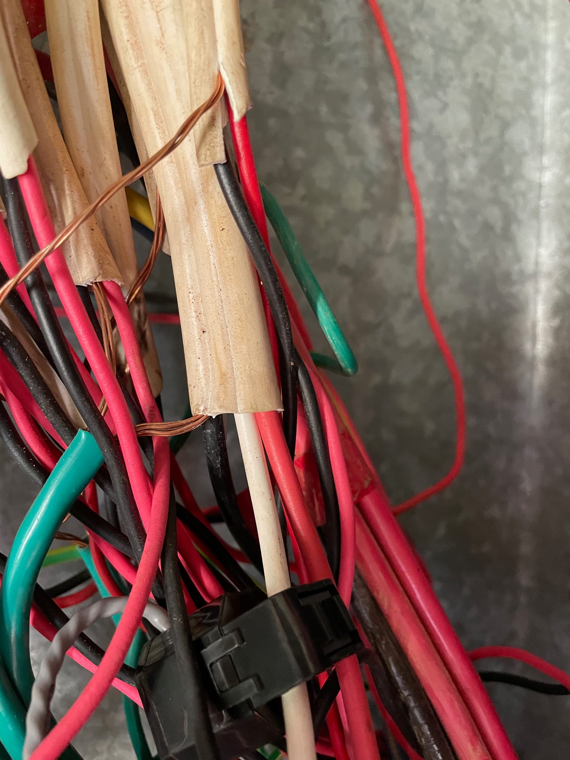
Here you can see the wider sheath in the middle of the picture with the bare wire (earth), black (neutral) and the red (oven) and white (induction stove) wires:

In the above pic I pushed the CT up along the wire a little to get it into shot. The CT (allowed to drop down the wire a little from the above photo) is around the white (induction stove) wire only:

.

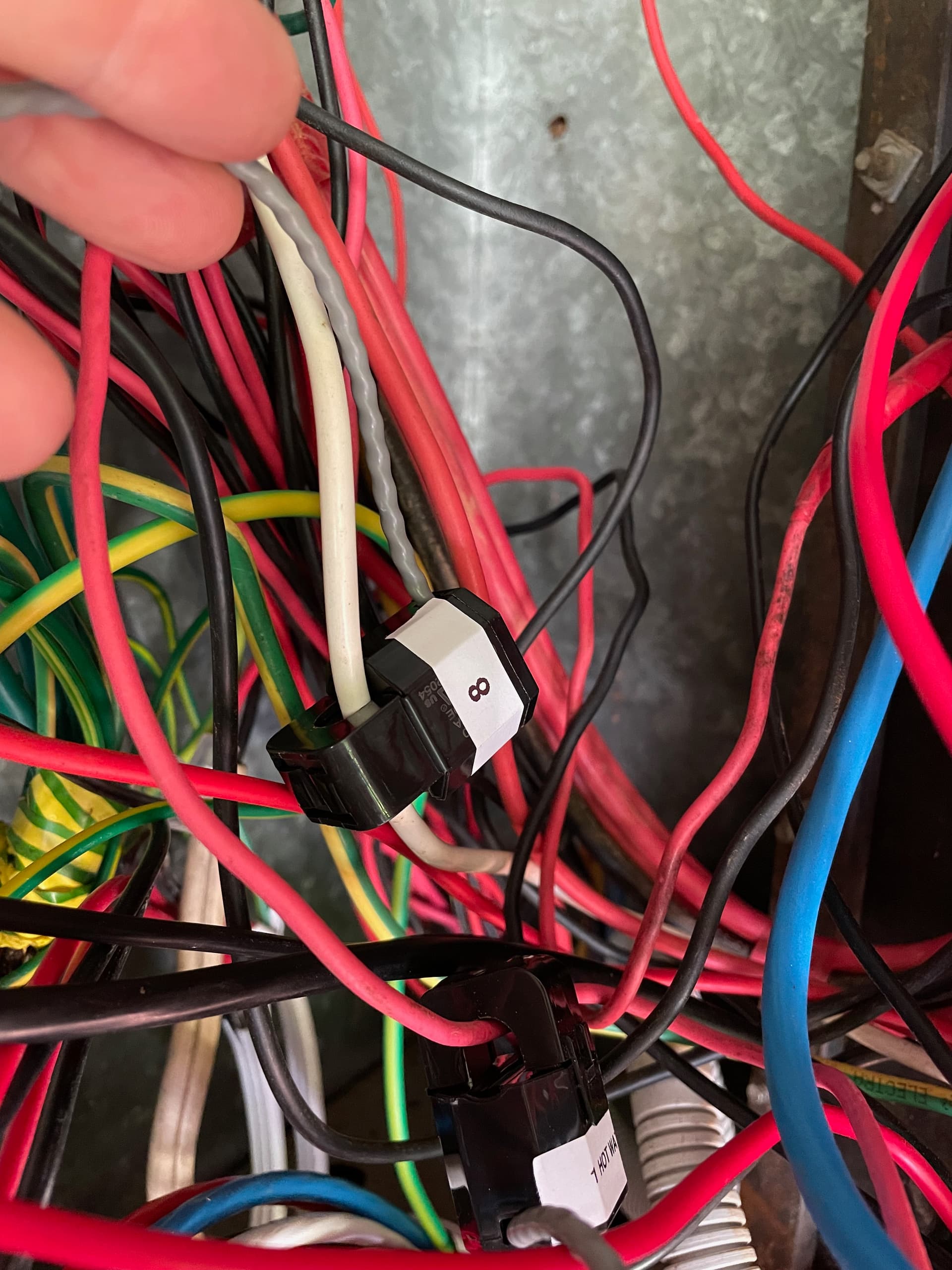
That CT is set to use the WHITE phase VT reference.

The colour code exception is the power supply cable to the mancave which use yellow instead of white. I confirmed this by looking at the 3-pole breaker used for that:
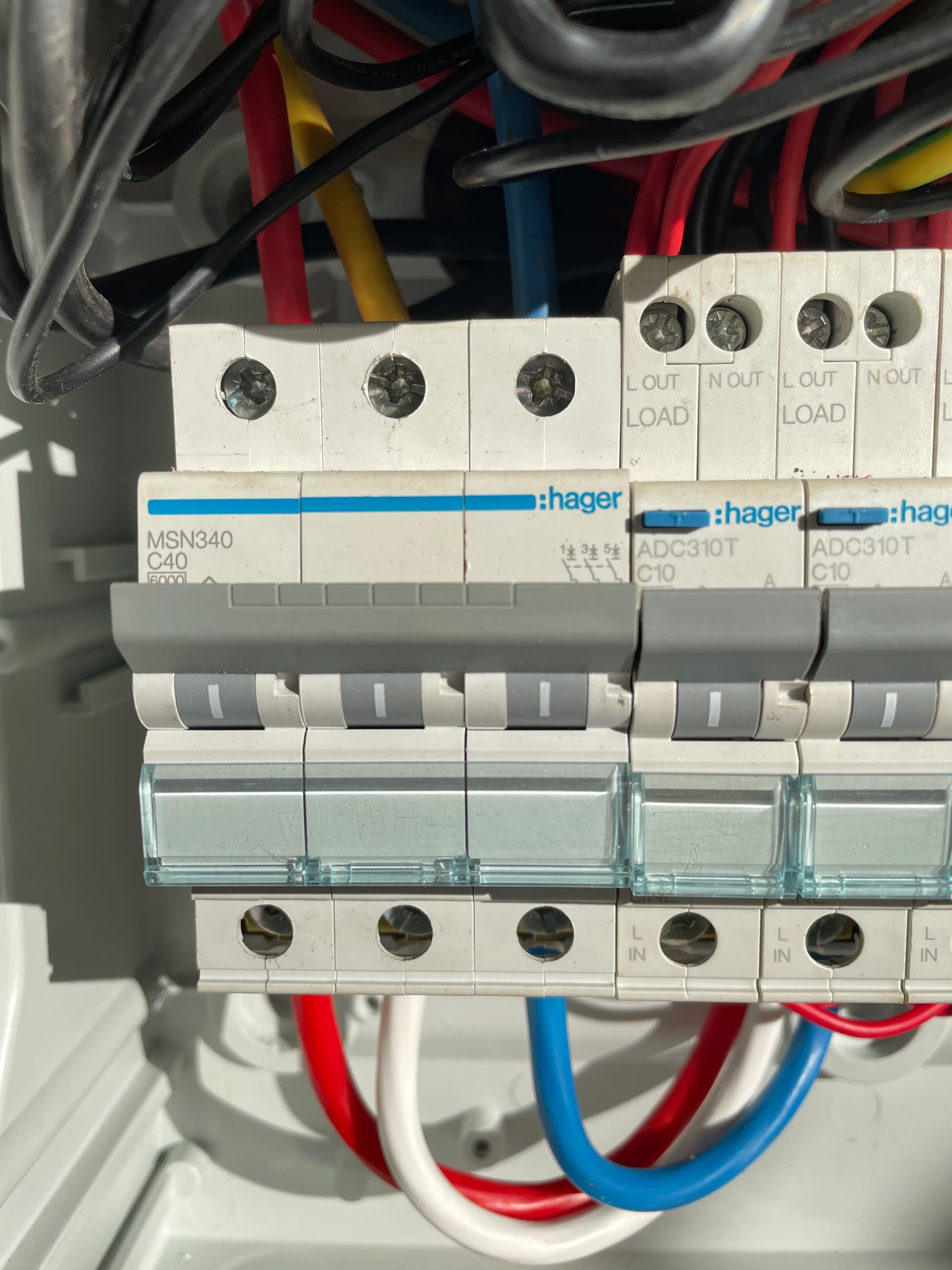
Red, white, blue IN
Red, yellow, blue OUT

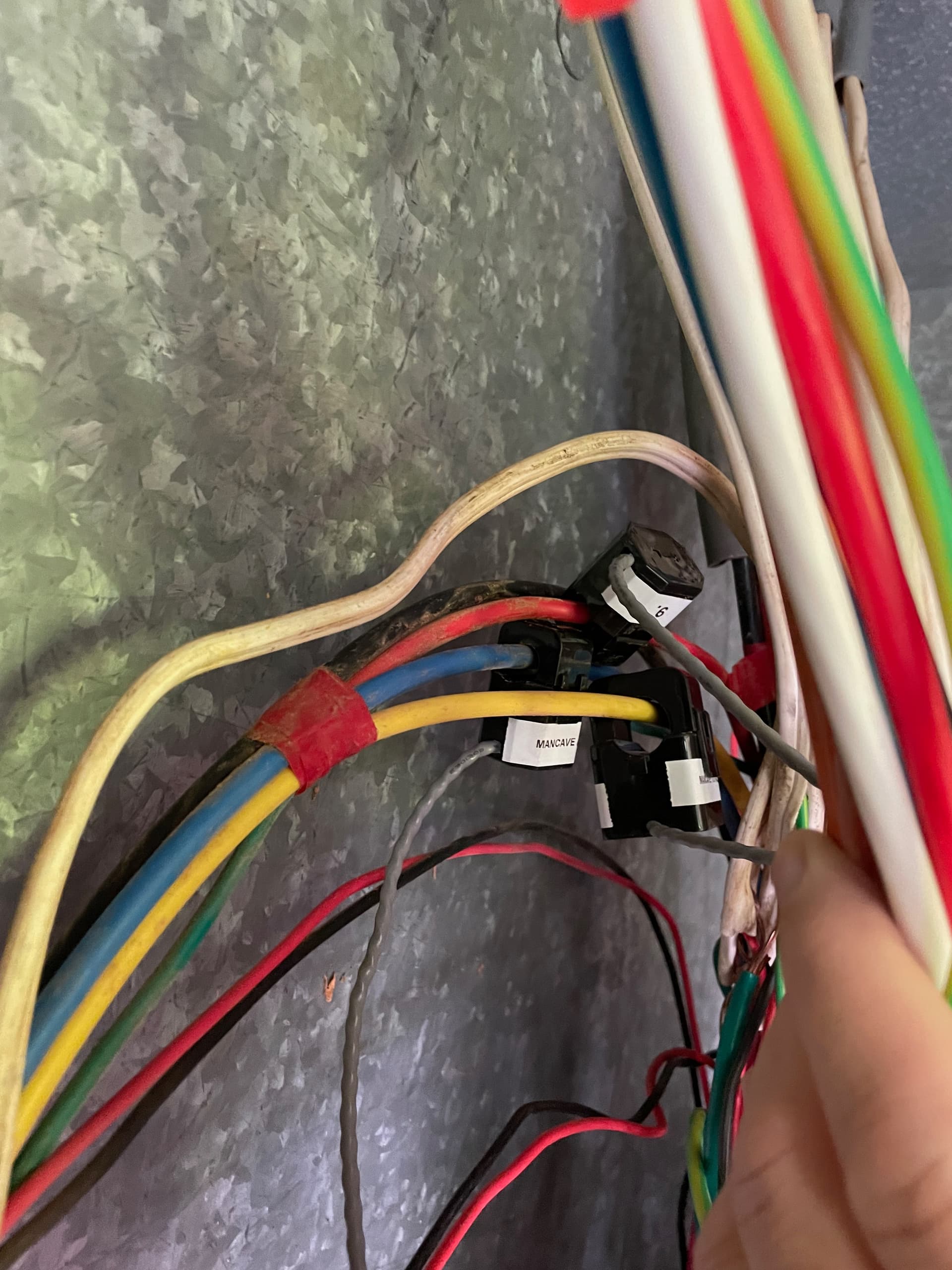
Here are the wires supplying my mancave, each with its own CT:

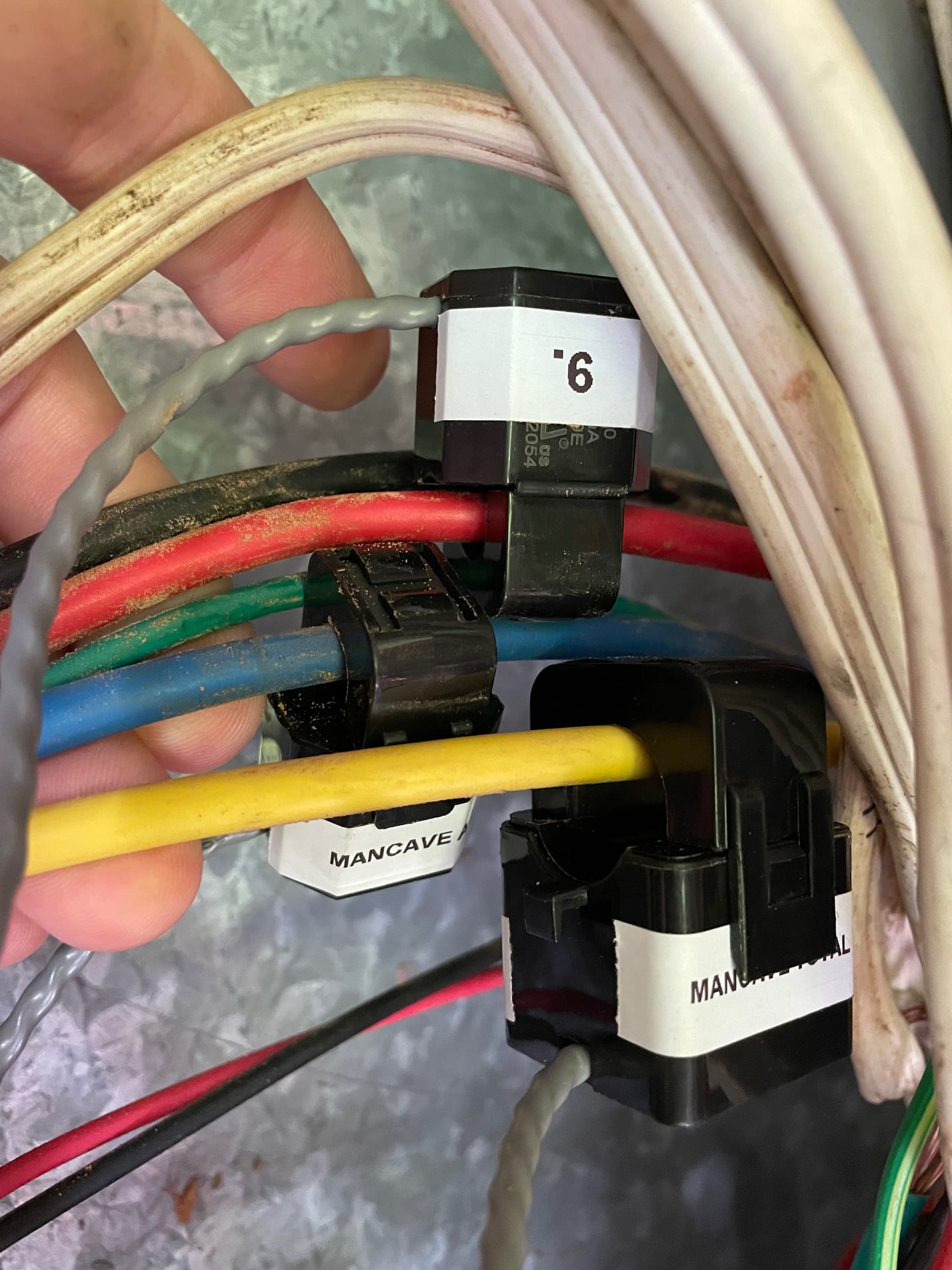
and here you can see them taped together, and a little further down they enter a sheath/conduit together like that:

Now the not so normal bit:

My home is supplied by a hybrid of grid and off-grid supply.

Circuits are split into two broad groups:
NON-ESSENTIAL: Those not covered by the off-grid supply
ESSENTIAL: Those covered by the off-grid supply

The NON-ESSENTIAL circuits includes electric water heater, ducted aircon, large split system aircon, oven, induction stove, 3-phase grid tied PV inverter, pool pump, and the input supply to the off-grid inverter (which itself can pass through grid power), plus the power outlets used by the VTs for the RED and WHITE phases. NON-ESSENTIAL circuits are only ever supplied by the grid power supply. If the grid is down, so are they.

The ESSENTIAL group is everything else, all power and light circuits and including supply to the two outbuildings and the power outlet used by the VT for BLUE/OFF-GRID phase and the power supply for the IotaWatt.

A break before make 3-phase transfer switch is in place such that when in the grid supply position, all circuits are powered by the grid supply and via whatever phase they are normally connected to. In this scenario if the grid goes down, nothing has power.

When the transfer switch is in the off-grid/backup position, then ESSENTIAL circuits are moved over to the off-grid supply. It’s just like having a backup generator set up. Meanwhile the NON-ESSENTIAL circuits continue to be powered via the regular grid supply.

In effect I have two isolated sets of circuits operating.

The phases of the off-grid supply side of the transfer switch are all tied together so as to form a single phase supply for all those circuits.

My normal mode of operation is to have the transfer switch in the off-grid position. It would only be placed back into the grid-only position if my off-grid system needed service.

The off-grid supply can supply/generate its own power (via a small off-grid PV array and a battery) but it can also pass the grid supply through (and its AC input is supplied via the BLUE phase). That is a remotely controllable setting managed by my Home Assistant automations.

Typically, the off-grid inverter passes through grid power during the daytime (as my grid-tied PV array and Fronius Symo inverter covers consumption), while in the late afternoon/early evening when the grid-tied PV is no longer able to cover consumption the off-grid system ceases passing grid power though and swaps over to power the home via the battery (which was being charged during the day by the off-grid PV array, and sometimes a bit of supplemental charging from the grid supply if there is spare grid-tied PV capacity). It’s all managed by Home Assistant automations.

So while I have two outbuildings which are supplied via 3-phase five wire cable (an earth, a neutral and the three actives), most of the time the power being delivered over the three actives is not 3-phase (with normal 120° phase angle separation), but rather the three actives are tied together as a single phase supply.

Hence the expectation a CT can cover more than one wire to the outbuildings.

And a couple of charts for comparison.

Here is the power over each of the three wires for the studio and the mancave:

STUDIO:

MANCAVE:

It’s the exact same set up for each, we can see the fridge power cycling in the Studio but cannot see the same in the Mancave.

I do not know why the charts have flat lined on the right.

I know the Mancave fridge is cycling, apart from it being on, I have that data separately from a smart plug:

The setup:

And a snapshot of the Status:

14 posts were split to a new topic: Wifi problems mesh router

That’s only a rare occurrence, e.g. if I need to take the off-grid system offline for maintenance or something like that.

In any case the RED and WHITE VTs will still be on their respective phase and be unaffected.

It depends.

If the off-grid system is in grid-pass through (Utility First) mode, then the grid supplies the phase timing. The power is a straight pass through.

If the off-grid system is not operating in grid-pass through mode, then the off-grid system is supplying the phase timing.

Which is why the BLUE phase VT is supplied power from the output of the off-grid inverter - so that the phase timing it supplies is in alignment with whatever the source of the power is, be it a grid pass through or generated by the off-grid inverter.

This is why I went with individual VTs.

So if I did need to flip the transfer switch back to grid-only (e.g. for off-grid maintenance), then in that time, I can either simply change the VT settings for those circuits back to their original phase, or not be fussed with having incorrect data if the downtime is short.

I would need to read this again in the morning after a couple of cups of coffee, and maybe make a line drawing (picture worth a thousand words - hint hint). But one thing that glares out at me is what appears to be needless complexity of the essential load handling.

Correct me if I’m wrong, but I think you are saying that the essential loads are connected to the three grid phases in one position of the transfer switch, but all three phases are connected to the Blue single phase in the other, which you say is “normal” mode.

I have to ask: Why not just make the essential system single phase all of the time? Then you would have a single-phase essential system and a three-phase non-essential system.

Another, probably simpler approach, would be to activate derived reference and use a derived Blue reference for any Blue loads on the non-essential side. Use of direct and derived are not at all mutually exclusive, in fact if any of your three-phase loads are three-wire, you can use derived reference to measure them with only two CTs.

You might need some Nodoze as well :slight_smile:

Ordinarily I’d agree. Hindsight is 20:20 and all that.

But I have what I have and there are various historical reasons including the power distributor wrangling I had to go through to get approval to build the second dwelling for my elderly mother, (who sadly passed away earlier this year). They required two things:

  • the second dwelling also have 3-phase supply
  • the entire property be capped to 32 A/phase

The whole thing grew out of the fact we average a dozen longer grid outages a year on average. I kept records of them all for years. Plus all the countless short duration outages.

With just the two of us here, I previously managed longer outages with a generator, a power inlet and the transfer switch and it was a reasonable effective way to deal with it.

But with the new dwelling for my mum (which I now refer to as the studio) and my work from home wife not being able to move/operate the generator, if I was not here then they would be without power and that was not acceptable to me. Aside from my wife’s work, it can get very hot here and heat can kill the elderly and that wasn’t going to happen on my watch. My mum in her twilight years was going to have the safety and power security she deserved.

So I set up an off-grid PV/battery system to replace the role of the generator. I found it worked very well and could be automated to do a whole lot more, so I expanded it.

And it works really well so why change it? I might even add more PV and battery to it but for now it does a great job. 10 kWh of LiFePO4 for daily cycling duties, 20 kWh of sealed lead acid data centre backup batteries in reserve for those extended power outages and we are not getting left hanging.

I had hoped the fact the outbuildings had three active wires each would enable some level of circuit level monitoring for the two outbuildings as effectively I have three individual circuits going to them.

But maybe the answer is to put it all ESSENTIAL circuits on BLUE phase, including running the outbuildings via BLUE only.

It would be possible. But would it be wise? I’ll have to think that one through.

Let me have a go. I am butchering a transfer switch wiring diagram.

Here is a 3-phase transfer switch diagram to show the way ESSENTIAL loads circuits are supplied:

And some photos. Under the transfer switch (ignore the 3-pole switch on the left - that’s the main supply breaker):

And from the top:

When switch is UP (GRID SUPPLY) then the grid supply is fed through to ESSENTIAL loads via R, W, B (shown on the actual switch as R, S, T) and all circuits operate as a regular 3-phase supply.

When the switch is down (OFF-GRID SUPPLY), then the single phase OFF-GRID supply is fed through to ESSENTIAL loads via G1, G2, G3, which are linked.

Naturally when the switch is in the middle position then neither supply is connected (break before make).

Now to make things fun, the off-grid inverter can generate its own power (using solar PV and/or battery), or it can pass through GRID power coming from the BLUE phase.

Naturally the circuit feeding the AC input for the off-grid inverter is one of the NON-ESSENTIAL circuits not supplied via the transfer switch (else I would have nasty feedback loops).

My “normal” mode of operation is for the transfer switch to be left in the down OFF-GRID position.

This means ESSENTIAL LOADS, which include the Studio 3-pole breaker plus this panel which also includes the Mancave 3-pole breaker:

are all getting a single phase supply via the off-grid inverter, be it grid power passed through the off-grid inverter, or power supplied by the off-grid inverter from the off-grid PV and battery.

I hope that all makes a bit more sense.

And to top things off, I seem to have weird Wi-Fi network issues (which I profess to not understand).

The IotaWatt is located near a mesh router for good signal. Even so, it seems to drop off the network and get lost. I do so wish it had an ethernet port to connect to. I grow weary of Wi-Fi hassles.

Today was a long outage between 9AM and 1:30PM.

Today’s log:

** Restart **

SD initialized.
3/22/23 02:06:23z Real Time Clock is running. Unix time 1679450783 
3/22/23 02:06:23z Reset reason: Software/System restart
3/22/23 02:06:23z Trace:  1:3, 1:3, 1:3, 1:3, 1:3, 1:3, 1:3, 1:3, 1:3, 1:3, 1:3, 1:3, 1:3, 1:3, 1:3, 1:3, 1:3, 1:3, 1:3, 1:3, 1:3, 1:3, 1:1[14], 1:2, 9:0, 9:0, 8:4, 8:6, 8:8, 1:3, 10:2, 10:3
3/22/23 02:06:23z ESP8266 ID: 15763621, RTC PCF8523 (68)
3/22/23 02:06:23z IoTaWatt 5.0, Firmware version 02_08_02
3/22/23 02:06:23z SPIFFS mounted.
3/22/23 13:06:23 Local time zone: +10:00, using DST/BST when in effect.
3/22/23 13:06:23 device name: IotaWatt
3/22/23 13:06:23 HTTP server started
3/22/23 13:06:23 timeSync: service started.
3/22/23 13:06:23 statService: started.
3/22/23 13:06:24 dataLog: service started.
3/22/23 13:06:24 dataLog: Last log entry 03/22/23 13:06:20
3/22/23 13:06:27 WiFi connected. SSID=Telstra25BEB0, IP=192.168.0.74, channel=6, RSSI -66db
3/22/23 13:06:27 Updater: service started. Auto-update class is MINOR
3/22/23 13:06:28 historyLog: service started.
3/22/23 13:06:28 historyLog: Last log entry 03/22/23 13:06:00
3/22/23 13:06:28 Updater: Auto-update is current for class MINOR.
3/22/23 18:55:00 WiFi disconnected.
3/22/23 18:59:11 WiFi connected. SSID=Telstra25BEB0, IP=169.254.166.136, channel=11, RSSI -80db
3/22/23 18:59:24 WiFi disconnected.
3/22/23 18:59:28 WiFi connected. SSID=Telstra25BEB0, IP=192.168.0.74, channel=1, RSSI -51db
3/22/23 19:07:09 Updater: Invalid response from server. HTTPcode: -4
3/23/23 00:59:33 WiFi disconnected.
3/23/23 00:59:42 WiFi connected. SSID=Telstra25BEB0, IP=169.254.166.136, channel=11, RSSI -76db
3/23/23 01:34:03 WiFi disconnected.
3/23/23 01:34:09 WiFi connected. SSID=Telstra25BEB0, IP=169.254.166.136, channel=11, RSSI -76db
3/23/23 02:00:24 WiFi disconnected.
3/23/23 02:00:28 WiFi connected. SSID=Telstra25BEB0, IP=192.168.0.74, channel=6, RSSI -51db

I don’t know much about networking but it seems like this device can’t make up its mind where to connect to.

Even so, is the data not still captured internally?

Thanks.

My 2.4 GHz and 5 GHz Wi-Fi have separate SSIDs.

My IotaWatt is ~2 metres from the mesh extender.

But it’s something I can try.

I still don’t fully understand your setup, and probably can’t without emmersing myself in the workings of your off-grid inverter (not going to do that). So, maybe there’s an explanation for this, but I find it strange:
image
The names imply these are the grid input to the inverter and the output to essential loads. Notice the power factor of the input. That can’t be right.

Both of these are configured with reference 14 or Blue phase. If I understand correctly from your description the VT is on the “out” side of the inverter. I think the output phase is produced by the inverter, and that any AC input is being converted to DC and then fed to the battery and inverter. I suspect the Blue phase out of the inverter is never the same as the grid blue phase.

I previously suggested that you try using derived reference for the grid side of the blue phase. I’ll give it another try. It would be pretty easy to do:

  • Check the “Enable derived three-phase” box in the inputs setup. This will not change anything with your direct reference setup.

  • Edit OFFGRID_AC_IN_4 to use Phase_RED for Vref, and then select “Mains Phase” B.

  • I suspect that with the correct phase reference, the power factor will be quite high. See if it’s .9 or greater. If not try setting to “Mains Phase” C.

Yes, it’s a good spot.

The issue is this:

The VT is using the off-grid inverter’s output voltage as reference.

When grid power is being passed through the inverter (e.g. daytime), then the AC input and AC output voltages match, and will be the same as the grid phase BLUE.

However when grid power is NOT being passed through, then the AC output voltage is is different to the AC input voltage. The output voltage will be what the inverter supplies (a steady 230 V) while the input voltage will be the grid phase BLUE.

Naturally in this mode there is almost no AC power being delivered into the off-grid inverter (although it does have a bit of annoying idle power consumption from the AC input).

I hadn’t ignored it, I just didn’t think it was possible to have both a VT and a derived phase voltage at the same time. I’ll have a go and report back, thanks.

OK, this is the new derived phase set up for the AC input:

And this is the set up for the AC output:

And the status screen:

BUT…

When looking at the data for the AC input and output power factors, it’s not reporting the output PF at all - or rather the data is stuck at a fixed value. See this chart:

Can see where I made the change to the AC Input and adjusted the phase angle adjustment setting a couple of times.

But the AC output PF is not moving - it is stuck.

It’s the same for the power output:

I see this across a number of the data channels - the data just stops reporting and it goes flat line at whatever the last value was.

e.g. the Studio power data did this yesterday:

and others show the same thing happening.

The status display that you posted with realistic Power and PF for both input and output was at 11:50. The plot you are showing with the “stuck” values shows good PF data at 11:50, and the “stuck” PF value for output is .93 which is what the status display says. Not saying there is no problem, but I don’t see the case for it. I don’t know what happened before 11:50.

OK, here’s what I mean:

If we look at the trace for the inverter’s AC power output (blue line) we can see long periods where it gets stuck at one value.

Meanwhile this is what the power output is actually doing over that same time period (as reported by the inverter):

Up until about 10:45AM the two charts are showing the same pattern for power output. But then the IotaWatt data just freezes at a fixed value and it goes flat line. Every now and then it moves to a new value and then flat lines again.

But that’s not representative of what the actual power values are.

The status page shows the same power output and PF value it was show several hours ago:

I’m trying to understand why this data just stops being recorded and just goes flat line. I’m seeing this happen in several of the charts. The time periods it occurs vary.

e.g. the PF for the AC output shows the same behaviour:

And another, here is the power values for the Studio today so far:

Just before midday the data stops being recorded and goes flat line.

Meanwhile the ducted aircon channel was capturing data the whole time:

Can you plot the three voltages for the same period?

Sure.

I do appreciate the assistance.

The voltage jump (blue) at about 8:30AM would be the off-grid system cutting over from supplying power from battery to passing through grid power.

Then just before midday yesterday (same as the other charts) can see the voltage also goes flat line.