Thought I’d share some pics of my new IotaWatt installation. Nothing spectacular, new or innovative.
I have a 3-phase mains supply, a 3-phase grid-tied PV system (Fronius) plus my off-grid PV and battery system. All integrated with Home Assistant.
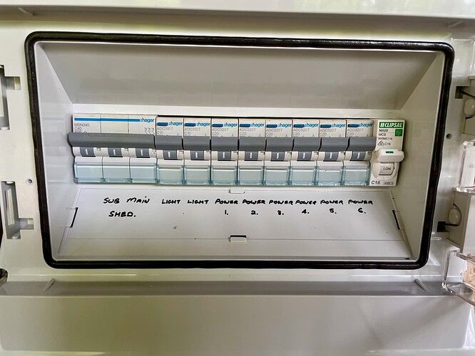
Aside from the main dwelling, there are also two 3-phase sub boards supplying power to a second dwelling and a large outbuilding (my mancave).
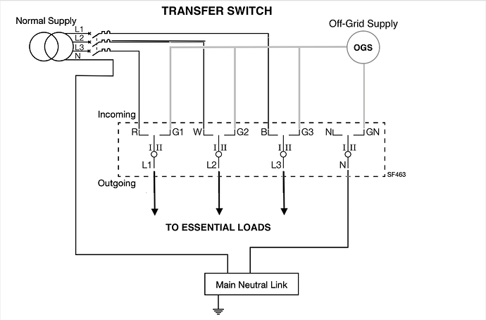
This combination makes life interesting as I have the home’s circuits divided in to “essential” and “non-essential”, where the essential loads are all powered via the off-grid system using a break before make 3-phase transfer switch.
The transfer switch is pretty much permanently set to the off-grid supply position but all loads can be cut back over to grid supply only if needed. Power to the two outbuildings is also covered by the off-grid supply.
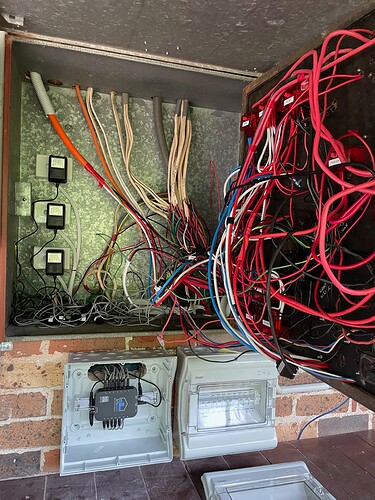
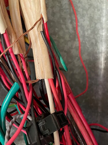
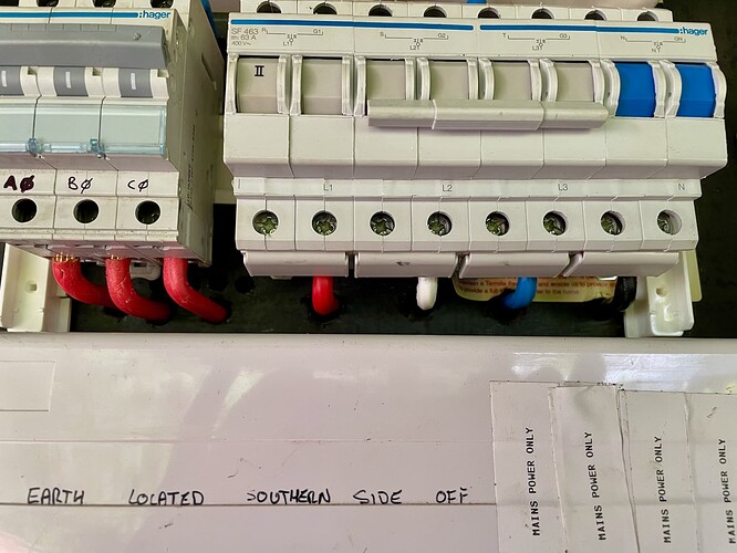
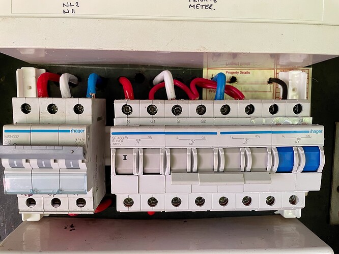
Anyway, after much work by the sparky to clean up the wiring:
I’m not kidding, that is after a tidy up.
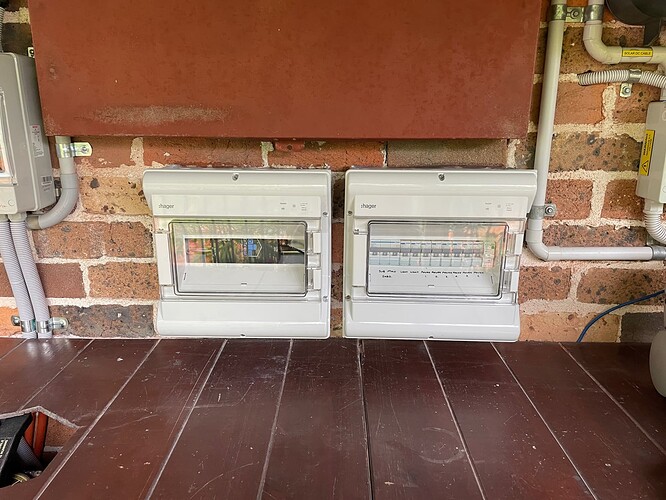
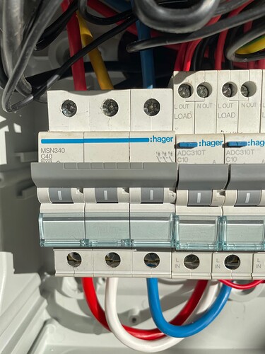
The IotaWatt sits in its own housing beneath the MCB, and next to the new essential loads circuit board. In the space to the left of the IotaWatt housing I will be relocating my small off-grid AC distribution panel.
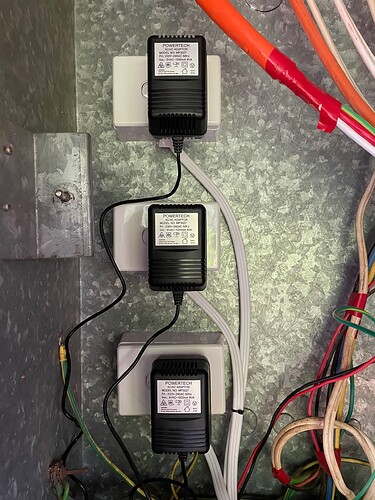
Inside the MCB you can see the new GPOs for the voltage transformers:
Which cover Phases Red, White and Blue/Off-grid. I went with individual VTs rather than using a derived phase voltage reference as our grid voltages experience quite wild swings, plus with the off-grid system it is often isolated from the other phases anyway, so I needed to cover it separately. Sometimes it passes grid power through (daytime typically) and sometimes it isolates and supplies its own power from the battery (night time typically). That switching is managed via Home Assistant automations.
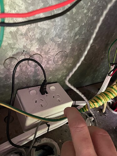
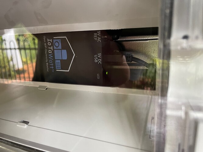
There is also a fourth GPO with a USB outlet to provide power the IotaWatt. This USB power supply is supplied via the off-grid system so it will remain powered during any grid outages (we regularly get outages).
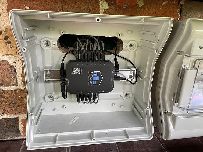
Here’s a closer look at the IotaWatt unit inside the housing after I had run all the cables through:
I have labelled all the CTs so I know which input they refer to.
It’s a generous sized housing, and if in future I thought about adding a second unit, then I think I can make it fit. It would be a bit of a squeeze but do-able.
With the housing lid/door on you can see the IotaWatt LED glowing, so handy for diagnostics without need to remove the housing cover:
And the final look with it all closed up:
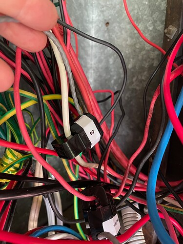
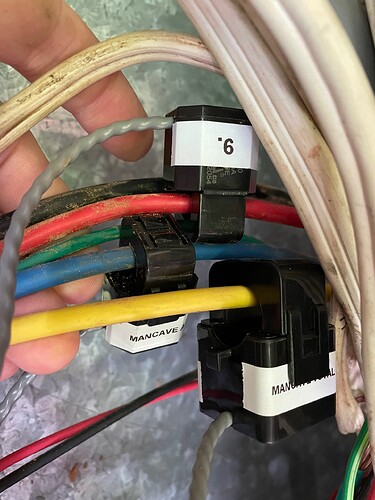
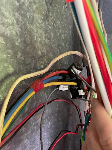
While all the CTs are connected to the IotaWatt, I have only clamped a few circuits so far.
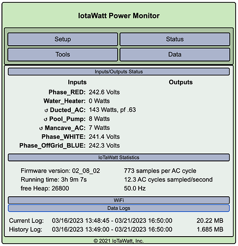
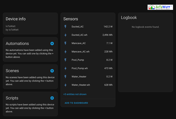
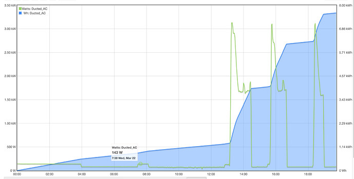
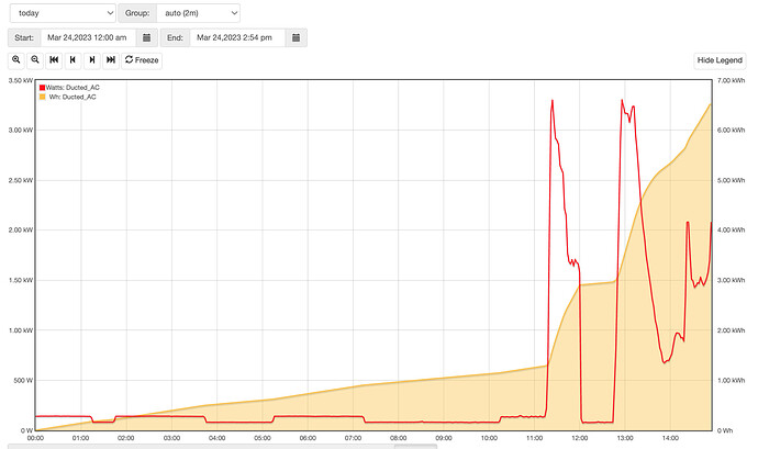
The ducted aircon, the water heater, pool pump and the mancave aircon.
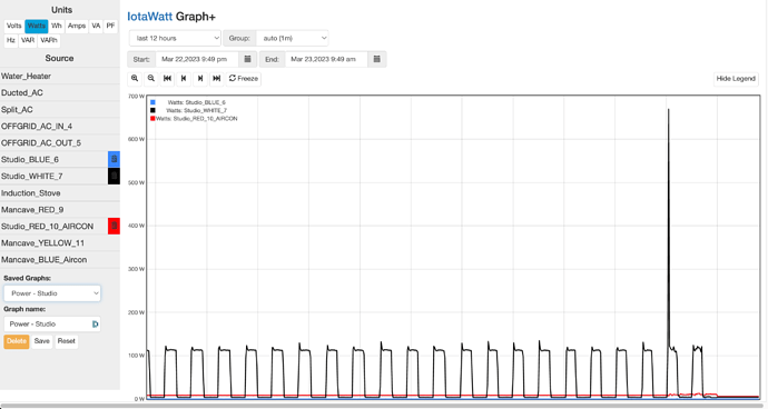
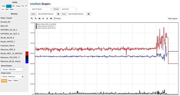
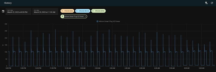
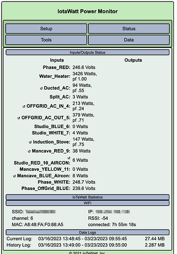
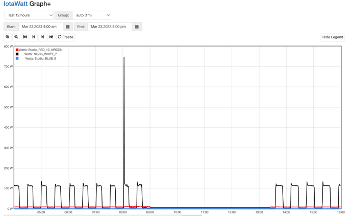
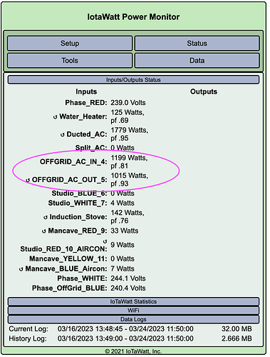
And the corresponding power and energy sensors in Home Assistant are showing up.
So will need to bring those into the Home Assistant Energy Dashboard and replace the derived sensor values I have set up for a couple of them. I should be able to now derive other power/energy numbers using a combination of metering inputs I now have.
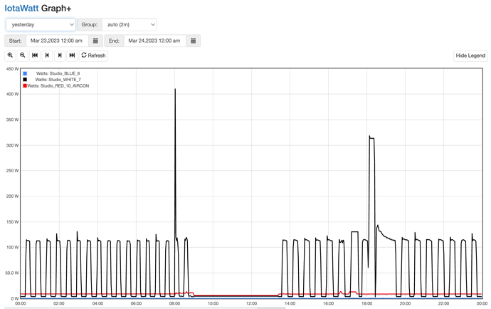
I will be most interested to see how the IotaWatt performs with measuring the water heater power. I have a smart PV diverter for the water heater (it operates by varying power delivered to the water heater to avoid any grid imports) and so the power delivery is rapidly being ramped up and down. Pretty sure my diverter uses burst fire method of varying power delivery.
I already get mains power data from the Fronius 3-phase smart meter and inverter, so the IotaWatt is mostly about circuit level monitoring.
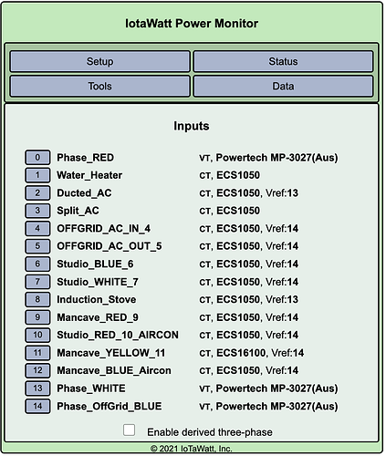
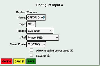
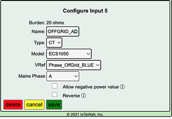
I have used seven of the inputs so far, three for VTs and four for CTs. So I have seven more to allocate. I have way more circuits than inputs so it’ll be a process of working through which circuits I want to capture, and if there are circuits I can sensibly capture with the one CT (e.g. I think my lights circuits are now on the same phase).
