The current phase correction in IoTaWatt is based on measurements at 60Hz. A good portion of the world is at 50Hz. The lower frequency increases phase shift on both the VT and CT, and if they have similar shift to begin with, there is little impact accuracy at 50Hz.
Nevertheless, we use some very low shift VTs (efficiency level VI) with some high shift CTs (SCT013) and visa-versa with high shift VTs (typically the lighter low-power models) and low-shift CTs (solid core). So there is a need to get it right all the time.
With the high sample rates of IoTaWatt, correcting the net shift error is straightforward and accurate. The problem has been getting base numbers for all the VTs and CTs at both 50Hz and 60Hz. I’m in North America, so I have native 60Hz. Awile ago, I acquiired a 50Hz true-sine inverter and have been testing VTs with it.
Problem was that my CT measurement device was 120V and could only push about 55 Amps anyway. Add to that how temperamental the rig is and hard to use with solid core and the problem was daunting.
I’ve been mulling the problem for months and collecting the necessary parts, so this week I started building. The heart of the rig is a 120V/230V transformer with 6V/12V output. For a load I use 24Ohm resistors in four banks of 1,2,4 and 8. With a four relay switch, I can produce 15 different loads.
On the other end, I wrap a CT with 1, 2, 4, and 8 turns of wire and connect those loops to the device where another relay bank can switch the multiplier from 1 to 15 turns. So at 6V the range is about 1-50A, and at 12V it’s 2-100A. With a 2x turns rig using 2, 4, 8, and 16 turns, I’ll be able to almost get to 200Amps. But that’s another step and I have to figure out how to beat the induction that many turns contributes to the measurements.
So I stuffed it all in an old stereo amplifier case:
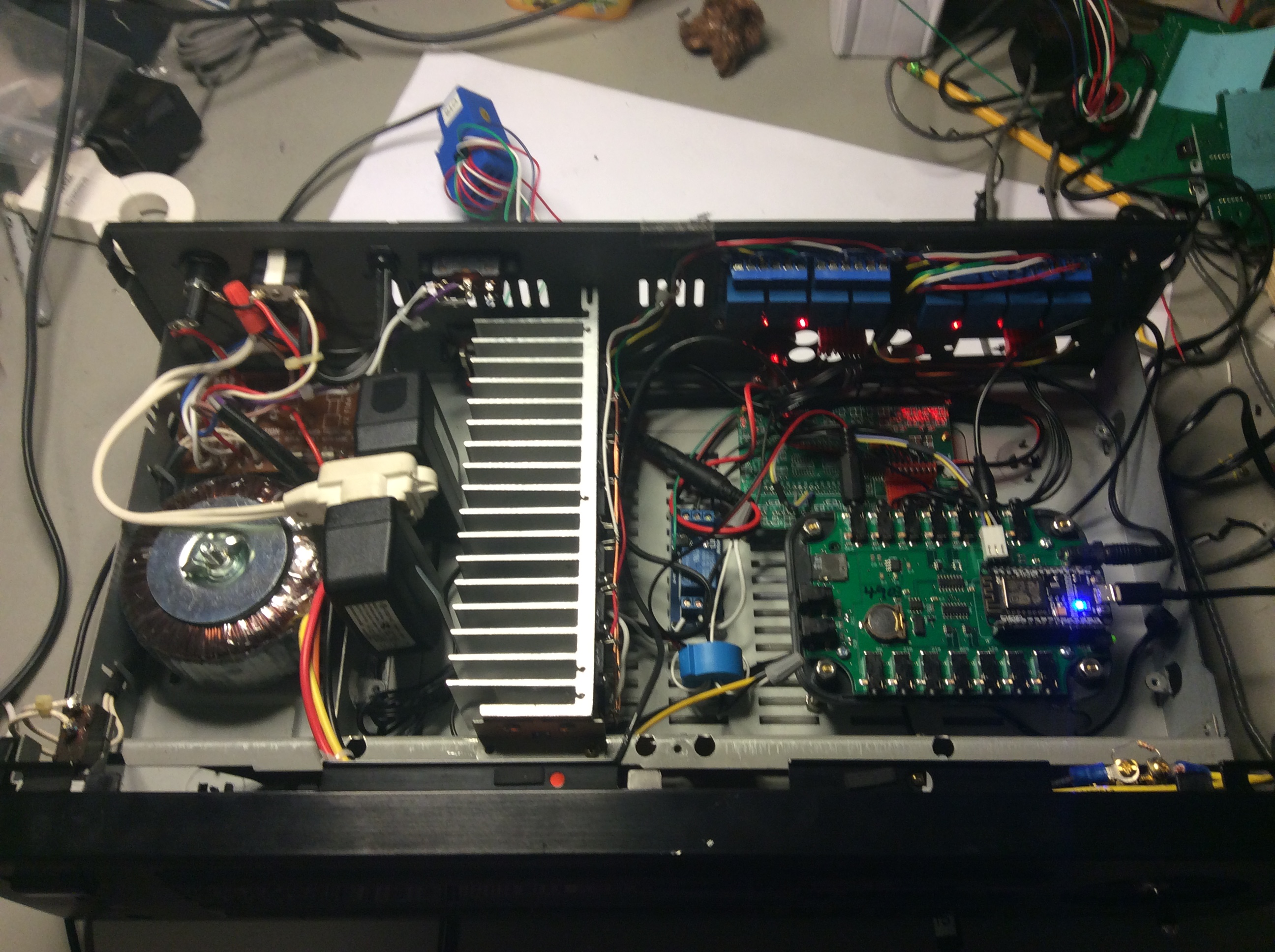
Notice the heart of the thing is… an IoTaWatt. It has an I2C header and connects to that daughter board with an IoExpander to drive the buffered relays. The big heatsink (from the original amplifier) is where the resistors dump their power. The high voltage is to the left of the heatsink. I use a couple of 100V-250v 5V power supplies so the voltage switch isn’t a problem.
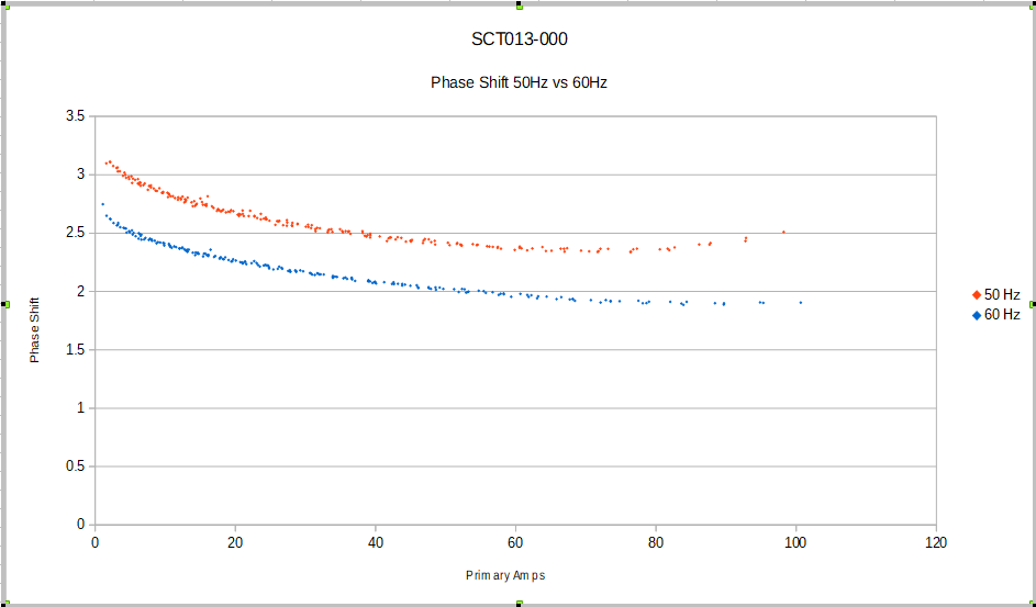
I still need to get a web-server working to control it, but using the serial link, I was able to calibrate it and run some tests. Here’s an SCT013-000:
And here’s an ECS1050:
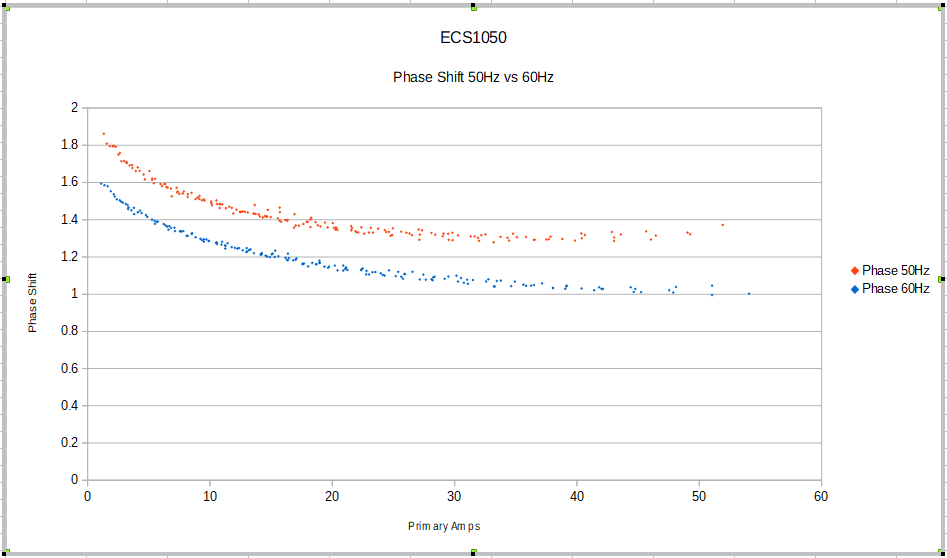
Both of these start to increase at about 80% of their range. That looks suspiciously like distortion to me. Both work fine to full range at 60Hz, but exhibit that upward trend at the high end of the 50Hz range. Not really a problem, but interesting. Both would probably be flatter at the end with a lower burden resistor. These tests were done with the now standard 20 Ohm IoTaWatt burden.
I’ll post again when I get it finished and start testing my collection of CTs at both frequencies. Ultimately, I’ll be programming IoTaWatt to correct based on frequency and probably use multiple corrections as a function of current.