New user puzzled by low readings

Very excited about this piece of hard/software that arrived today, but can’t seem to get started.

Quick facts:

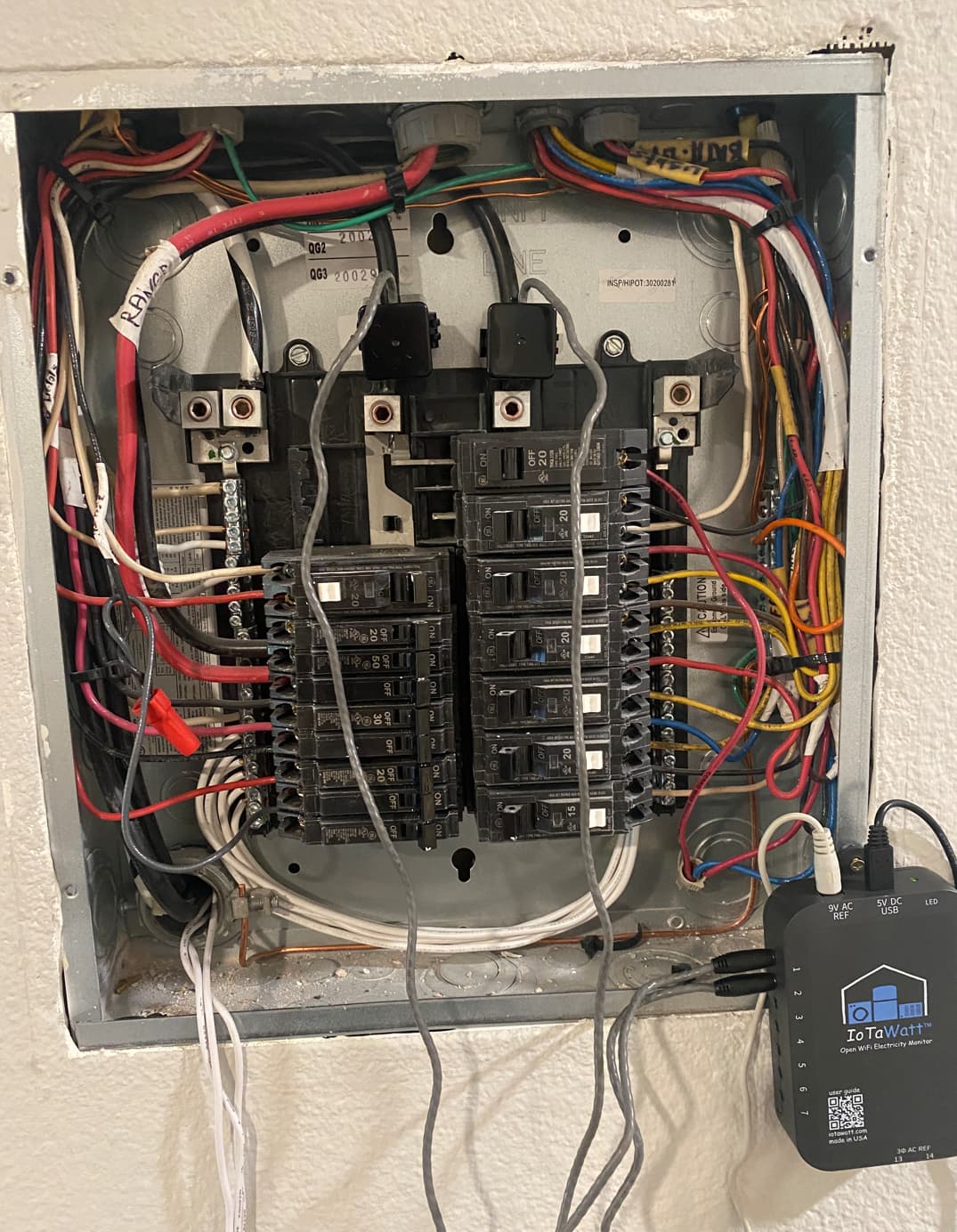
  • New IoTaWatt system with 2x AcuCT-H063-100 and a JW-95001-NA (+ provided USB adapter) plus a bunch of other CTs still in the box.
  • Live in a standard US apartment with split 110/220v power, nothing special
  • Engineer with decent EE understanding and previous experience with horrible (accurate but unreliable) z-wave energy monitors.

Problem:

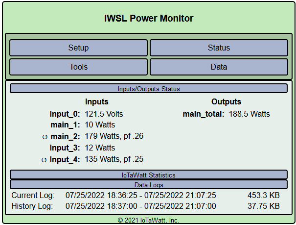
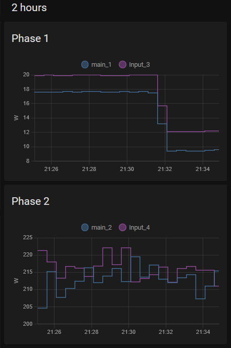
  • 1 CT is constantly under-reporting by a lot - it states constant 10-20W when each phase is usually over 100w at least
  • If I turn on the garbage disposal (which feeds from the “faulty” phase), it constantly displays <250W (it’s a 3/4hp motor). My electric kettle measures just about right 1600W with the “good” phase, but <1200W with the “faulty”, so it doesn’t seem like a linear issue.
  • If I swap the CTs, the “faulty” CT will bring the problems over, so the affected phase will suffer now
  • Now here’s where it gets interesting: if I connect both CTs to the same phase, they display +/-10W!

The whole this is obviously under-reporting (main1 + main2 don’t even add up to my 3d printer measured outlet).

Attempted troubleshooting

  • Read, re-read and re-re-read the CT’s model numbers against my configuration
  • Squeezed the CT tightly with no change
  • Physically and virtually reversed both clamps
  • Was ignored about my huge issue by my spouse

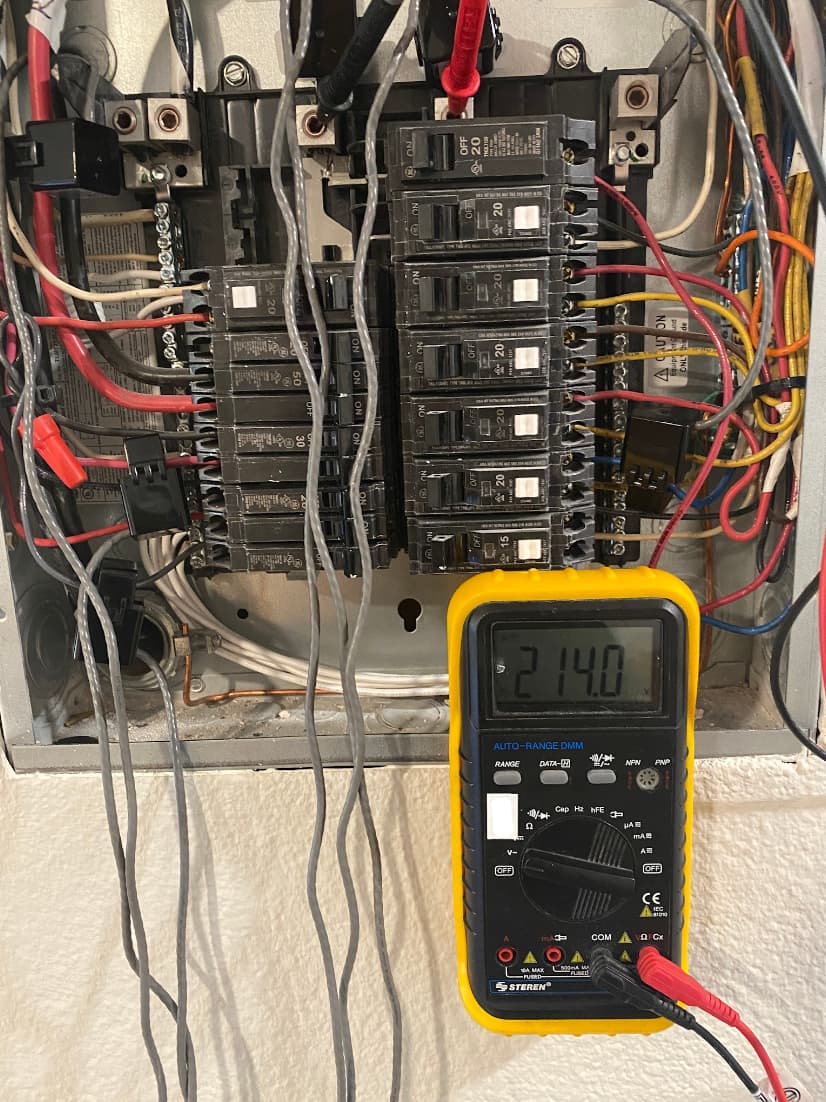
Thanks in advance. I have also provided a pic from my setup and config. Order #127095 (July 18, 2022), if it makes a difference.

{
	"format": 2,
	"timezone": "-8",
	"update": "MINOR",
	"device": {
		"name": "IWSL",
		"version": 3,
		"channels": "15",
		"burden": [
			0,
			20,
			20,
			20,
			20,
			20,
			20,
			20,
			20,
			20,
			20,
			20,
			20,
			20,
			20
		]
	},
	"inputs": [
		{
			"channel": 0,
			"name": "Input_0",
			"type": "VT",
			"model": "JW-95001-NA",
			"cal": 11.14,
			"phase": 0.74
		},
		{
			"channel": 1,
			"name": "main_1",
			"type": "CT",
			"model": "AcuCT-H063-100",
			"phase": 0.6,
			"turns": 2000,
			"cal": 100
		},
		{
			"channel": 2,
			"name": "main_2",
			"type": "CT",
			"model": "AcuCT-H063-100",
			"phase": 0.6,
			"turns": 2000,
			"cal": "100.0"
		},
		null,
		null,
		null,
		null,
		null,
		null,
		null,
		null,
		null,
		null,
		null,
		null
	],
	"outputs": [
		{
			"name": "main_total",
			"units": "Watts",
			"script": "@1+@2"
		}
	],
	"dstrule": {
		"adj": 60,
		"utc": false,
		"begin": {
			"month": 3,
			"weekday": 1,
			"instance": 2,
			"time": 120
		},
		"end": {
			"month": 11,
			"weekday": 1,
			"instance": 1,
			"time": 120
		}
	}
}

Update:

Added two 50A clamps exactly next to main_1 and main_2 100A clamps. Two thoughts:

  • There’s some consistency, at least, though a 44W difference in <200W sounds alarming?
  • pf seems super low?
  • [main_1+main_2], as well as [inputs 3+4] are still much lower than my household power, with many lights, monitors, computers, NAS, 3D printer (138W measured), etc plugged in.

image

I also connected to Home Assistant, and I notice that the difference between both sets are not consistent: phase 1 looks like a semi-consistent offset, while phase 2 seems still biased but with more noise:

I don’t see your mains breaker in that box, leading me to believe it’s a branch panel. I see that your voltage is120V on each leg, but is it possible that your service is120V/208V? That is sometimes done in apartments and condos with three-phase main feeds. It would explain the non-VT leg being low with low PF, and any 208 load being low. If you have a voltmeter, simply measuring the leg-leg voltage should verify that.

Thanks you for such a quick reply. I do live in an apartment complex with dozens of units per building. I measured the busbars and it measures 114V on my meter (which may not do accurate RMS).
Would adding a second VT be an option? I assume I’d end up hard-wiring the second one to the panel which may or may not be up to code.

You need to measure the voltage between the two feed legs. If it’s 208V another VT can correct your second main but won’t help with 208V circuits. There is an easier solution, but first let’s verify that is the problem.

Yep, I meant 214 but typo’d 114. Measured again, 214V (from my not-fancy meter)
My leg-to-netural bars measure 124v, which is indeed a sqrt(3) factor.

OK, lets fix it. You have a three-phase service sans the third phase. IoTaWatt can use derived reference (one VT) or direct reference (in your case two VTs). I would recommend derived as the 208V loads must be derived anyway. For reference, IoTaWatt handling of three phase is documented here.

Start by insuring that your mains CTs are oriented the same way, with the arrows pointing toward the panel. Insure that all of the branch CTs are also oriented the same way but with their arrows pointing away from the panel. This step is very important.

Check the “Enable derived three-phase” box at the bottom of the input setup display. All of the inputs will then have a phase designation. Initially they will all be phase A.

Phase A is defined as the leg where the VT is connected. Identify that leg and the associated main CT input. The other one will be either phase B or phase C, you don’t know at this point. If the phase A mains CT shows a negative value (or the reversed sign) in the status display, reverse the VT - either physically in the socket or virtually by checking it’s reverse box.

You mains phase A CT should now be reading correctly.

Change the other mains CT to phase B in it’s setup menu. Plug in a known resistive load to a circuit on that leg and turn it on. The mains B should increase by the known load amount if it is phase B. If it is phase C, the increase will only be about half. If that’s the case change it to phase C and retest. The power should now be as expected and both mains should be correct.

Now you will need to go through the branch circuits and assign the correct phase to each. The 120V circuits will be A and (B or C). The three 208V circuits on the left are connected between the two phases.
If they connect to a two-wire load (no neutral), then put a CT on one of the wires and select phase A-B or C-A as appropriate. If the appliance is a three wire load, then put a CT on each conductor, assign the phases as appropriate, and create an output to add them together.

Good Luck.

3 Likes

Hats off to you, @overeasy . I was bummed when I though my post had gotten buried, but I just missed the notification email.

I went through your instructions and it works! In the process, I also found out that my apartment is super imbalanced, phase-wise.

I was hesitant for a while to get this product instead of trying to fix my crappy Aeotec z-waves or DIY, but I’m very glad I did. This is next-level support, so thank you.

1 Like

Hello @overeasy , I have a followup.

I went over the documentation, but I couldn’t reach a conclusion as to what’s the best way to combine circuits into one CT clamp on a derived 3-phase (in my case, minus 3rd phase apartment system).

Case in point: kitchen circuits. They’re each on a different phase, and aren’t at all correlated. I thought about passing the cables through one CT with opposed polarities, but I don’t think they’re opposed, but partially offset instead. I assume we can’t aggregate such circuits with one CT, but I wanted to check.

I did a ‘delta’ output (phase A - phase B) of both dryer and range, and it’s usually 0, occasionally up to 8w, so I decided to just do AB and save a CT. Since this sounds like a software implementation of aggregating equal but offset currents, it made sense to me to just monitor one phase.

Thank you