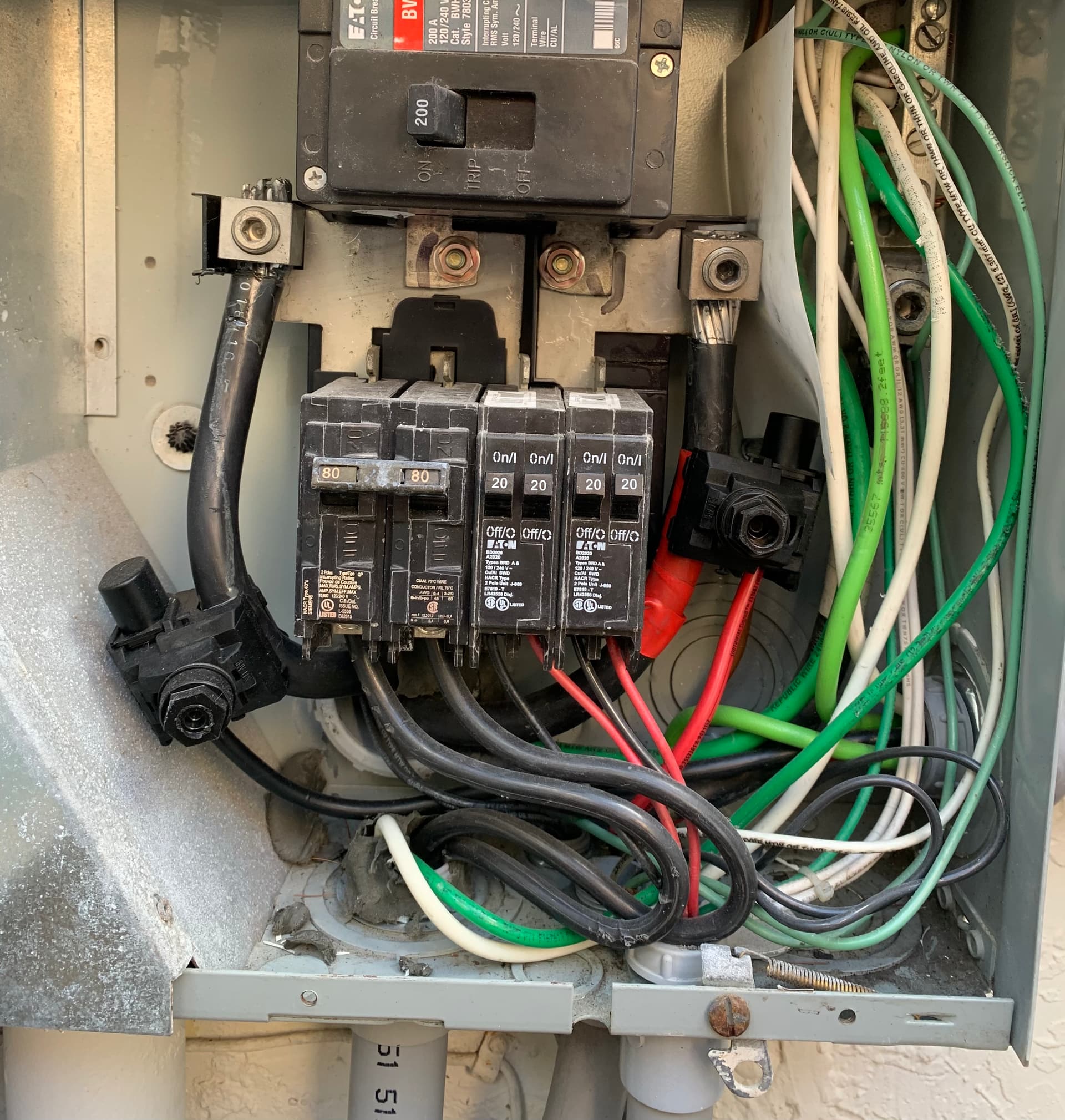
As can be seen in this photo, from my meter and main breaker to these outside breakers I have no cable to attach a CT clamp. I have the cables going into the house main electrical panel and the solar connected to these. What’s the best option here?
My thought is that I should clamp between the meter and solar connectors. Then get additional clamps to measure those extra circuits. I’d like to avoid wasting iotawatt inputs. For the solar I can get the data from my inverter so also don’t want to waste inputs for that if possible
No matter how you slice it, you will need to know what those breakers in the meter box are using in order to get an accurate measure of what you are importing and exporting to the grid. If you want to know how much energy you are using, you will need to measure the solar inverter output. Once you accept that, the problem is reduced to how to do all that using the minimum number of inputs.
So, starting with Main Panel, you can put conventional CTs on the two main panel feeds upstream of the solar connections. Any solar contribution will reduce the measured load to the point of back-feeding when solar exceeds the main panel load.
It looks as if you may be able to measure the local circuits with just two 100A CTs. The leftmost 80A breaker and the two leftmost 20A breakers are all on the same phase. They appear to pass by each other right where the fat one takes a U-turn to the left. You may be able to put a 100A CT around all three at that point. Similarly, the wires from the rightmost 80A breaker and the two rightmost 20A breakers come together just at the same point in the U-turn of that fat black wire.
So that would give you all of the data to measure your grid import/export. If you want to also know how much energy your solar is putting out and therefore how much energy you are actually using, you will need to add 2x50A CTs to the solar cables. It’s possible you can get by with one, but you would need two to determine that initially.
If you want to measure the usage of that 80A 240V load, you would need to add 2x50A CTs to measure the 20A loads.
To sum it up:
2x200A for the main feeders to the panel
2x100A for the local breakers
optional:
2x50A for the solar
2x50A to measure 80A 240V circuit individually or if cannot get 100A around all of the wires.
EDIT: To measure the 80A individually, you can get by with one 200A CT and 2x50A for the 20A circuits. There is enough room to pass the two wires through in opposite directions. If the cables are 8mm or less, you can probably use a 100A instead of a 200A.
Thanks for taking the time to write that detailed response! Really appreciated. I’ll need some time to digest it all
I probably want to measure that 80A individually anyway, since that’s all my pool equipment. So I’ll see what I can get away with to hopefully measure all those other 20A ones with one CT
I’ll definitely need to move my 2x200A CTs to here, upstream of the solar as you say (they’re currently inside the house on the other panel, but that doesn’t let me see what is going back to the grid.
For the solar, I’m trying to get away with not measuring it with IotaWatt, as I have it as a separate measurement in HomeAssistant. But I know this will get tricky trying to calculate the consumption vs production in HomeAssistant, whereas IotaWatt makes that relatively simple. I’ll keep the CTs on the solar as a backup plan. If I do have to do it with CTs, is there a reason I can’t use a single CT with one cable running through in the opposite direction?
If inputs are the issue, you could combine the two 50A into one input with a headphone splitter.
If you have CTs on the downstream end of those cables, you only need to monitor the solar.
That would work. First, I would try using two 50A to see if the two are equal. If so, you can use one 50A and double.
With the 200A that you already have inside, one CT on the 80 Amp, 2x50 on the 20A combining with a splitter, and one CT on the solar would use three additional inputs.
Just one quick question on this, I thought the docs said each CT needs the capacity to handle everything it’s combined with when using a headphone splitter. So here with 4x20A wouldn’t 50A ones be insufficient?
The issue is not over-driving the input, so yes, 4x20A is 80A. But a 20A circuit is supposed to ordinarily operate at 80% or 16A. That’s 4x16 = 64A IoTaWatt has about 15% headroom so it can handle about 57A from a 50A CT. Unless you are mining bitcoin or running four electric heaters, it should be OK.