Noise from one device bleeds to another?

I’m getting everything set up the way I like pushing metrics to an Influxdb and Using Grafana for the graphs. One question I have for example when my dryer comes on at the same time there will be a much lower wattage mimicking the dryer wattage at the same time frame on another device. Is this normal or one device receives interference from another? Please see picture. …Well I don’t see and option to upload a picture…

While barely significant, that is interesting, and if you want to work with me we could try to figure out where this is coming from. Yes, it’s possible that there is some communicative effect inside the IoTaWatt that cause this to happen. I kinda doubt it, but easy enough to narrow it down. First, I’d like to see the configuration and what kind of CTs are used by both circuits.

I’d like to see you move this circuit to a different input on the IoTaWatt, preferably on the other side so it is using a different ADC. If the problem moves with the CT to the new input, then I would look at something going on in the panel like the CT for this circuit being right next to the CT or wiring for the Dryer.

If it doesn’t move, then I’d like to see another CT plugged into the original input and see if it does the same thing. If it does, then I would agree that it could be one input effecting another.

Either way, I think it’s amazing that you are getting that resolution on the outdoor light channel to record 1.75 watts in such sympathy with the dryer. My money is on an external factor.

I will will get this info for you and try moving the input to the other side and post that result this evening.

Thanks.

Here is the config where we see the dryer and outside lights next to each other resulting in the above graph. Second picture I switched input 10 (dryer) with input 4 Well…I will let it generate some data and see what happens now. Thanks.

OK,

Unrelated, you might want to review the documentation on 120/240 Volt circuits. Just doubling the value for the range, and probably the dryer, will probably not be completely accurate. Those appliances use both 120 and 240 Volts, so both conductors must be monitored. You can do it by passing both through the same CT if you observe polarity. Read the discussion referenced above.

Thanks. I knew the range this was needed and had to order another CT because the wire is 4 ga. (to large) I will get a two into on adapter as explained in document to connect. I didn’t know the dryer was like this as well and just fixed it. Thanks for your help.

Okay, Here are some pictures of today with he dryer moved like suggested. As you can see the riffle is on other branches as well even the barn in a diff sub-panel. I’m not complaining or seeking support, I think the IoTaWatt is amazing and what I’ve been looking for. I’m going to try flipping the hot water heater off and see if the dryer affects it like that. Notice the outside lights are smooth no affect at all. Strange.

It looks like it may be something going on in the ADC. I took a close look at my data with the dryer running and I can see something similar. Funny I never noticed it before. Like you, some circuits seem to be immune. One twist with my system is there’s one that appears to be negatively effected:


Then I’ve got another that seems to be effected several times as much as the others, and that one has three circuits running through the CT. So It may be inductive cross-talk or it may be in the ADC. I’m going to open up my panel and take a closer look at the CT and wire paths.

The negatively effected circuit maybe explained by the voltage drop in your mains associated with turning on a large load. Lower voltage means other circuits will show lower power consumption. Depends on the impedance in the utility network upstream from your board. In my case the LV mains are long and the effect is quite noticeable as you can see below when the hot eater heater turns on.

Well, there’s your problem. You probably should have something that gives up heat not takes it in for a heater :wink:.

But, good point on the lower voltage causing a difference. I see a change of less than half a watt on some circuits that are basically nothing (less than a W) when water heater turns on 2.5-3k to 1 difference, ie close to 1 bit out of 12.

Voltage drop does not explain where the shape is in sync across two circuits. That is if they both go up and down at exactly the same time then it looks more like some sort of lack of signal separation whether at the CT, CT leads on in the Iotawatt.

Yes the “hot eater heater” is an interesting concept.

Flying purple people eater

1 Like

I actually have one of those. The hot eater water heater that is. It is a heat pump water heater and it eats the heat of the surrounding area and gives it to the water. I have had it for over a year and it does appear to save a significant amount of energy, but I have it set so it runs 16 hours a day.

I’m thinking there may be some current leakage in the TVS diodes. IoTaWatt uses 4 channel rail-to-rail TVS ICs, so groups of 4 (0-3, 4-7, 8-10, 11-14). My dryer is on 6. I see this on 4 and 7, but not on 3 and nowhere on the other ADC (where the drop was). I’ll be doing some experiments.

and @frogmore, @Giraffe,

I did some experimenting this afternoon, and narrowed this down a lot.

First, I focused on my oven/stove circuit which measures 2 240V circuits by passing all of the conductors (black one way, red the other) through an SCT013-000 (been there for years). This CT comes in port 7 with the dryer in port 6.

When I start the dryer, the oven/stove goes from 6 watts to 16-17 watts. I tried it in multiple inputs on both ADCs. Same thing.

So I dragged the oscilloscope down there and hooked the probes up to a 3.5mm jack with a 22 Ohm burden. With the dryer off, I saw a little under 1mV at 60Hz. When I turn on the dryer, the value jumps by about 1mV.

Lets do the math. The SCT has a calibration of 100, which means that 1 Volt across the burden is 100 Amps primary. So 1 mV = .001V x 100 = .1 Amps. .1Amps x 120V = 12 Watts - just about the increase I’m seeing.

My conclusion is that the problem is external to the IoTaWatt. It’s reporting what the CT is telling it. I tried removing the CT from the cables but leaving the CT cord running through the load center and the problem went away, so I don’t think it is anything with the cord. The two (4) CBs for the oven/stove circuit are in the upper right of my load center and the dryer is in the upper left. The cables do not come anywhere near each other, although they do run near the mains, which also carry the dryer load.

My main panel has been running these CTs for years. There is an eclectic mix of CTs - SCT013-000, CR3110, HWCT-004. I have been meaning to redo it with Echun CTs. Maybe that will have an effect on this issue.

I intend to try various turns ratio CTs to see if it’s actually current in the wire or the CT. In the meantime, there’s nothing that can be done in the IoTaWatt.

Thanks for sharing this information. Like I said this isn’t a problem. I was just curious. Thanks again.

I’m glad you brought it up and that I was able to resolve it. Had it been something inside the IoTaWatt, I would have considered it a problem.
Thanks

I was seeing similar bleed-through on my IotaWatt I just installed. Among the other circuits, I was using an ECS1050 on Input8 to measure my 120V washing machine and an ECS16100 on Input6 to measure my 220V oven. Both of the hot leads went through the ECS16100 (entering the current transformer in opposite directions) to measure the total oven current. I was seeing around 31W reported on the washer (even with the washer’s breaker open) when the oven was drawing 3706W. The power waveform of the washer matched the oven except for having different a different amplitude. I noticed while looking at my IotaWatt’s status page that the 31W reported on the washer was reversed when the oven was on (no power should have been consumed by the washer at that time.)

My washer’s CT was in close proximity to the hot leads of the oven, so I thought I might be able to add some distance between them to reduce the bleed-through. Moving the washer’s CT didn’t help. Even though the washer’s CT (clamp-on type) was completely closed, I noticed that when I squeezed the top and bottom of the CT, the power reported on the washer would drop to zero. I ended up wrapping some electrical tape around the CT to create some compression on the clamp and now the washer reports 0.5W (as expected) when the oven is on.

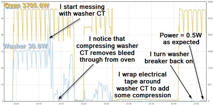
My theory on CTs isn’t that good, so I’m not sure why compressing the CT’s clamp would have such a big effect. Maybe compressing the clamp decreased the electrical resistance between the split cores and reduced the effect of external magnetic fields generated from the oven wires? I tried it several times just to make sure that was what was reducing the bleed through. I haven’t taken a detailed look at my other CT’s, but the washer and oven combo was one that stood out. Graph of my troubleshooting shown below.

image

3 Likes

I can’t explain what is happening, but since you found a solution I can offer some tips to address that issue.

First, without a doubt, solid core CTs are superior in almost every respect. They cost less, they have less phase shift and they don’t have these mechanical issues. The downside is that they are more difficult to install.

By far, these ECS1050 CTs are the best seller, and are working well. That said, out of thousands, there are things that could go wrong and you might want to take a closer look at a problematic one.

All CTs need to have an unbroken iron core around the primary conductor. Solid core CTs use a solid “doughnut”, but split core used two “U” shapped halves that have finely machined and polished mating surfaces.

These surfaces must be clean and without chips or deposits. You can clean them carefully, but if there are mechanical imperfections, they will not work properly. Examine the exposed parts of the two halves and push on them gently with your finger. Try to see if they may be cracked. A cracked core will still work somewhat but not accurately. They are made from very brittle iron and could be cracked if dropped or whacked, even slightly.

Now note how force is applied to the upper half when closed. There are a couple of plastic tabs in the top that bend slightly:

The force applied by these should be adequate for the mating surfaces to be in good contact, but if the latch doesn’t provide enough closure, maybe not. That seems to be what is going on in your case (if the core isn’t cracked). So one thing I have done in the past is to shim those pressure tabs. I cut a narror piece of box cardboard and fit it for size, then trim it to fit.

This might work as well as electrical tape, retain the ability to remove, and just look a bit neater.

1 Like