Some Dryer Readings Assistance

I’ve searched for ‘dryer’ and read those posts (like this and this) but am still unsure why my readings are what they are.

Dryer is on a double pole 30A breaker with a black and a white conductor.
Currently have a 50A ct on each. I want to combine them with a splitter eventually but need to make sure I understand each individually first.
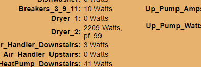
Here are my inputs:
image

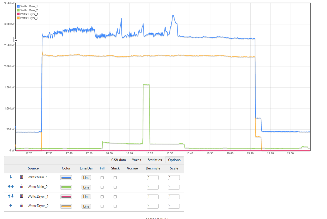
Here is the status on Tumble (no heat):
image

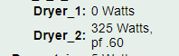
Dryer_1 never showed anything.

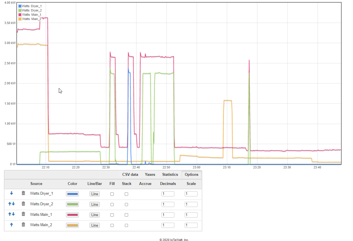
Here is on the ‘Normal’ cycle:
image

Dryer_1 still doesn’t show anything of real value.
As seen above, sometimes it shows that it’s reversed even though it isn’t. The presence of the reverse icon comes and goes. I actually haven’t seen it for awhile. Assumed it’s the motor being a generator but haven’t really focus on the icon much since the [lack of] readings are the bigger issue.

I’ve moved the CT from Dryer 1 to another single breaker, plugged a lamp into it and confirmed it shows wattage so CT looks good. I’ve also flipped the CTs (Dryer 1 to Driver 2 and vice versa) but same thing - the white conductor doesn’t show anything or it’s negligible.

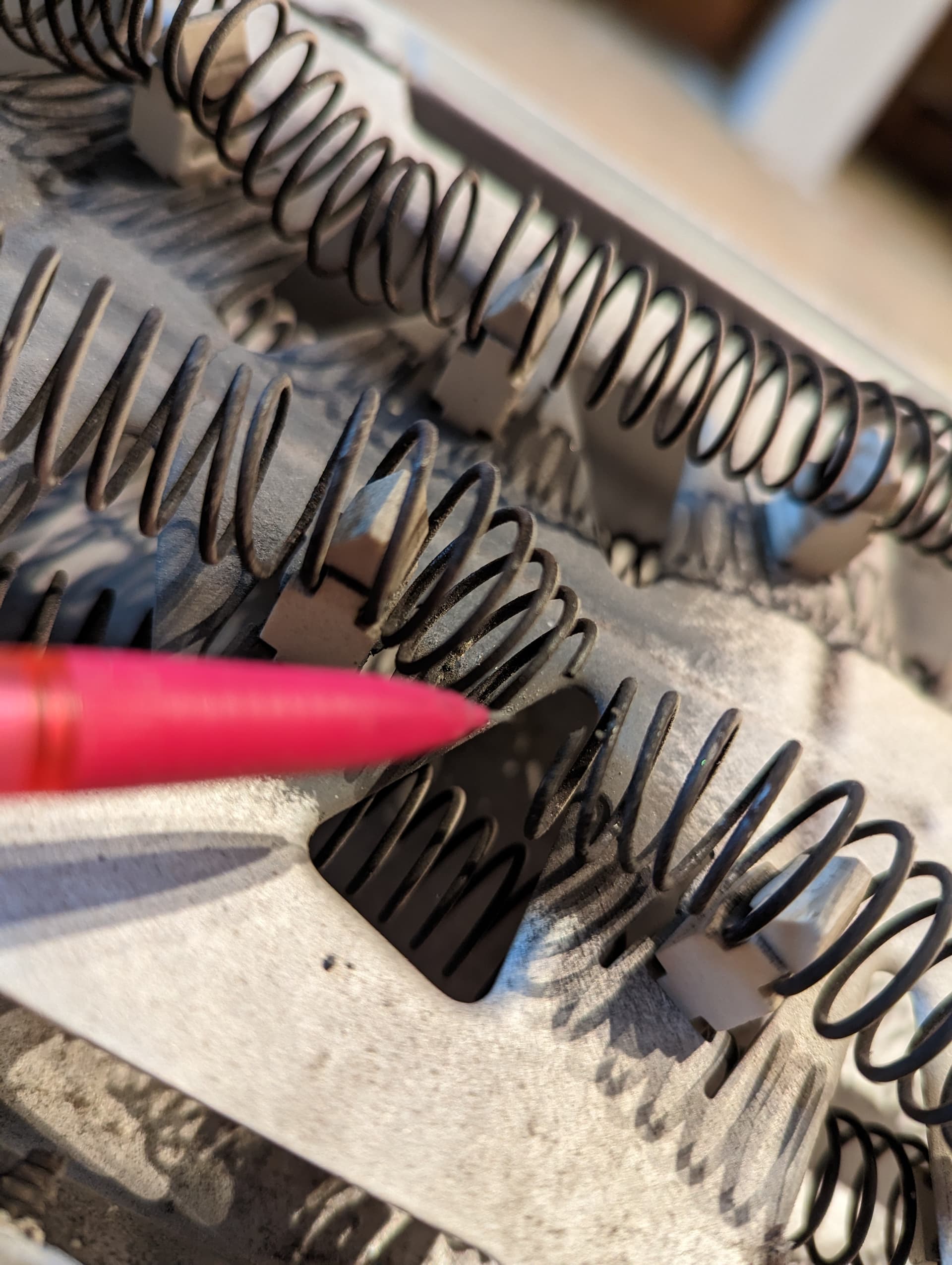
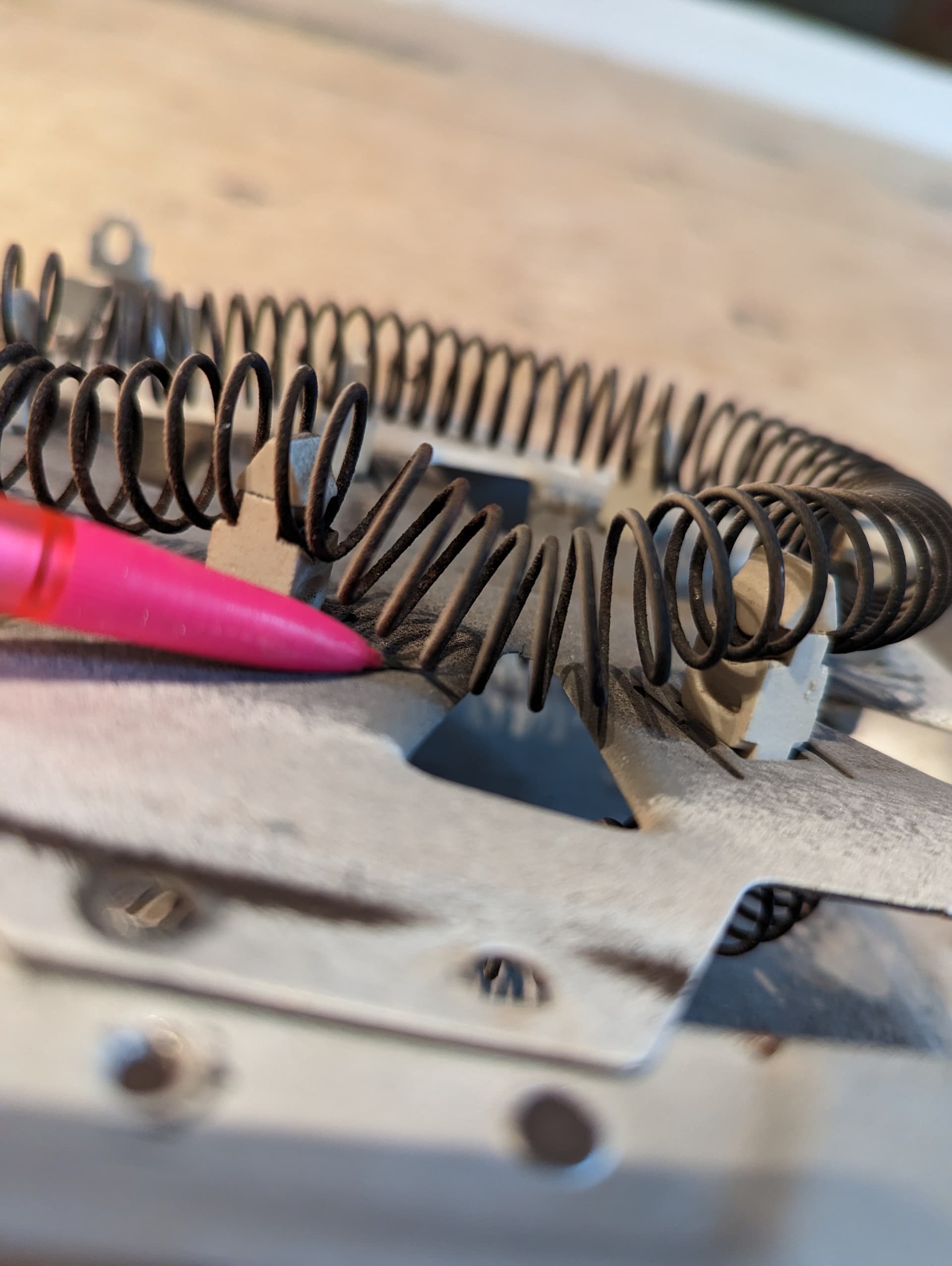
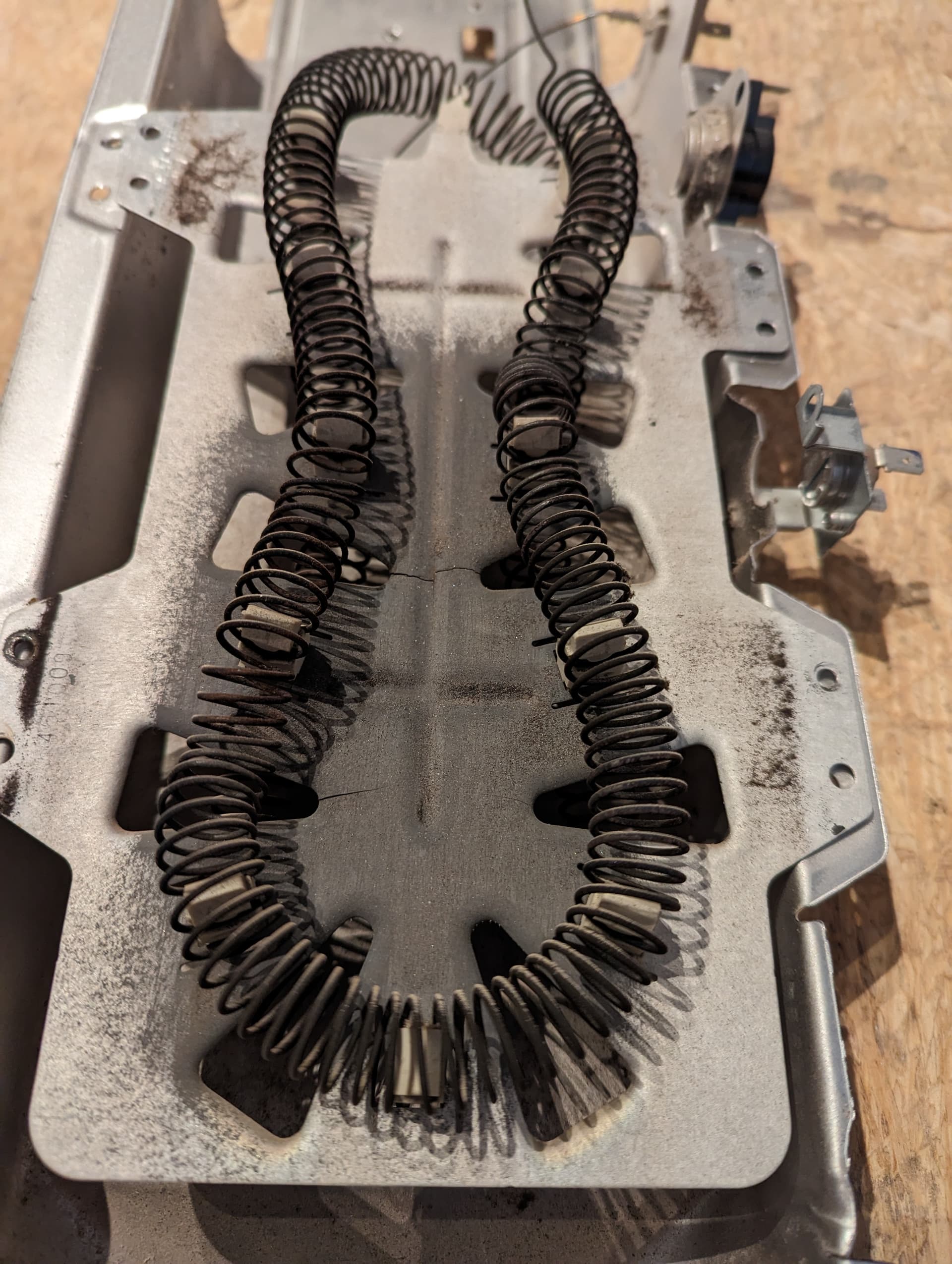
We did have issues with the dryer awhile back and I replaced the motor and belts. It’s drying the clothes but I am getting the feeling that the IoTaWatt is clueing me into something else that’s going on with it.

Can you post a pic of the breaker with CTs?

Gladly.

Top White = Input 9
Bottom Black = Input 10

Current status of the dryer running right now on a Normal cycle is:
image

I have also flipped CTs to the different Inputs and the readings flip appropriately.
It appears that the white conductor never sees any wattage values like I’d expect.

I pulled the dryer and confirmed voltage was present on the two hots. I didn’t check actual voltage value though :unamused:

I think this may be a wiring issue with your dryer cord,plug or socket, based on the assumption that the white is actually zero when the dryer is running. Do you have a voltmeter? Any junky voltmeter would do. Can I see a picture of the plug and socket? Can you trace those red and black to where the leave the panel and verify that there is not a red conductor in the cable?

Edit: Can you also show a plot of your mains and the dryer 1&2 that shows it starting and going through a complete cycle? No need to run it, just look back for the last time it ran.

Oh shoot. I meant to mention that as that’s a key point. I’d looked at that also. Since I hated to ask you to diagnose my dryer, I posted first on DIY here :smiley:

Don’t feel obligated to read that thread but if you do, 99% sure the blue spike in post #6 was me swapping the CTs since the wattage is always on Main_1.

Here is a graph of it running with the mains.

That green spike on 2 is a POU 6gal Water Heater.
Main 1 has a high baseline due to the pellet stove running as well as a server/switch.

As seen Dryer_2 is on Main_1 with the usage reflecting this.

Dryer_1 is on Main_2 and for better or worse the usage also reflects this.

I’d need to pull the washer and dryer again to take photos but it’s a 3 prong setup. Same with the voltmeter test at the plug. They are boxed into a cabinet with a counter on top so not a quick process.

These wires get tucked pretty deep behind everything so can’t visibly trace them in the box but definitely no red wires in there. House was built in 78 fwiw.

After watching some videos and reading some diagrams, the only thing that makes even a little sense electrically is that the heating element is broken/bent and grounding to the frame yet didn’t trip any internal fuses.

Unless something stands out to you in the graph I guess tomorrow night I’ll be tearing the dryer down.

When I look up the dryer model that you specified in the DIY forum, it states that the dryer is 120V/240V three-wire. From what you say, there is no red or third conductor. I hope this is not the case, but if there are only the two hot conductors, and one is not handling any current, the ground would be completing the circuit. That’s not just wrong, it would be a huge safety issue because if the ground should become disconnected, the entire unit would be energized to 120V.

Try harder to identify the cable in your panel that is the dryer, and verify if it is two or three wire. That is exclusive of ground which would be bare or green.

If you can identify the dryer ground wire, try putting the Dryer-1 CT around that and see if it shows zero or the same as the Dryer-2 CT when you start the dryer.

If you pull it out, be sure to turn off the breaker until it is unplugged and you are ready to test the voltage.

The manual states the unit is shipped without a cord. there are several opportunities to wire it incorrectly, both in the receptacle and connecting the cord to the Dryer. While you have it out take pictures of the receptacle, with the breaker off remove the receptacle cover and take a picture of the wire connections and take a picture of the cord to dryer connection.

For reference:

Will do! Interested to see what this ends up being.

The usage doesn’t add up. Most standard dryers (not the heat pump kind) use a single element that uses 240V. It is possible that your dryer is wired incorrectly.

this image:

Shows some significant 240W usage on both mains (but nothing on the dryer) in the first block.

The circuit labeled dryer2 (which is the same side as main1) appears to have consumption that looks like a heat pump with heating element, but is only using one leg, since main2 has no corresponding usage.

The circuit labeled main2 has similar usage, but at a different time, but could be the superposition of two different loads.

From 22:40 to 22:55 or so, the picture is also strange. Dryer2 appears to be most of the load of main1 for most of the period, But, dryer2 goes to zero for a min or more and main1 doesn’t show that, which is very strange.

I don’t believe you have things hooked up the way you have IotaWatt configured.

I would double confirm the breaker labeled dryer is actually the one connected to dryer. It is generally a code violation to have a white wire connected to a breaker. A standard 3 wire 30A dryer circuit should have 2 hots and a ground (that is also used as a neutral). It is possible in an old house that this used 2 wire + ground NMC cable (Romex is a brand). The white wire should have been marked with black/red tape to indicate it really is a hot wire.

When trying to figure out these types of problems, I graph both mains and also all the other circuits (and stack those ones) that shows me the left overs. That makes it easier to figure out where not to look, if it doesn’t identify the exact place the power is being used.

In your picture of what you say is the dryer working normally and dryer2 showing 2200W. That is about half of 4500W, so it might be true, but main2 is not showing any usage for part of the time when the dryer is running. That isn’t possible if the dryer is using 240V. If the dryer is only using 120V (because it is wired incorrectly), there is no way it is using 2200W. The 240V element would only draw about 1.1KW at 120V. I suspect you have multiple configuration errors. I would start with making sure the mains look good, then work on the other circuits.

Despite having decent electricians doing the work, my panel had some circuits mislabeled and I have had a circuit miswired more than once (but in those cases it was obvious, because the breaker blew immediately).

I posted the schematic above. The PCB is a black box, but notwithstanding @frogmore observation that running a 240V heater at 120V would reduce power to 25% or 1325W (5300W heater) + 325W motor = 1,650W, I wonder if the dryer deliberately goes to 120V on the heater when delicate/low temp is selected. On my dryer the temp setting just cuts the 240V heater at a lower temp, but this unit appears to have three settings and I have to wonder if they go to 120V heater for the lowest setting. In any event, can you check to see that your temp is set to high?

The schematic is not very definitive, but seems to indicate that the heating element gets the voltage from L1 via the connector #3 at PCB (black wire from L1, blue wire to element via two safety cutouts). It then gets L2 (red) via the centrifugal switch on the motor. That seems to indicate the element is always on 240V.

I would (and did) focus on the mains first. They do not appear to be telling the correct story right no now. When I was figuring out things, I would run around the house with a mobile device and turn loads on an off to see the impact directly on the mains. This is very visible with a large load. Smaller loads can be much harder.

This is the usage of what is labeled as Utility 1:

It took me quite a while to figure out that ~10W jump in the base from 5PM to 8AM. I searched everywhere in the room for what it might be. Turns out it was the landscape lighting in the front yard. The outdoor outlet in the front of the house is on the same circuit as the utility room.

Looking at the wiring is not a bad idea, and you might still need to do it to really figure out what is going on.

Yes, the PCB does supply the other end of the heater through 3.2. It was a long shot, but possibly it could energize that terminal with either L1 or N, depending on whether delicate heat is selected. IMO it would be a more elegant way of providing low heat with less cycling between extremes. Worth taking a glance at the unit settings before taking things apart.

I have to wonder why they didn’t just make the L1 connection outside of the PCB? Seems like they wanted some control there.

Thanks guys.
Mains are good. Took my 100W spot light around and confirmed Main_1 and Main_2 both reflect ~100w increase when I plug it in to a circuit on their leg.

Confirmed I was on High Heat for the test cycle.

Checked voltage at the breaker. Both conductors good. ~120v
Flipped the breaker and pulled the dryer out
Confirmed wiring of the whip and checked continuity along it. All good
Flipped breaker on and checked voltage at the plug against the ground at the plug. Both hots good. ~120v

Going to open the dryer now.

Check if hot to hot is 240V?

Ah yes. 242v to be exact :grinning:

Now if only they could make the edges of dryer sheet metal a little sharper.


That doesn’t look good, but it still doesn’t explain the power signature you were seeing. There is probably more to the story.

Well there you have it.
Broken coil PLUS a portion sitting on the [grounded] casing. So really 2 issues or possibly one caused the other?
Can really see how the sheet metal has gotten hot and cracked.
Guessing the watts used by the one leg was all dependent upon how far into the coil it was being grounded?

And it would have gotten away with it too if it weren’t for that meddling IoTaWatt!
Well for a while longer anyways…

Thanks both of your for your help. Much appreciated.

1 Like

Sorry frogmore, was typing while you replied.

Can you elaborate on why you think there is more to it?

Sorry, you are correct. I missed the broken coil part. I think you found your problem. Time for a new coil or perhaps dryer.

2 Likes