Hi There,
I recently configured my iotawatt setup for a 3 phase installation in Australia. Unfortunately after installing everything I found out that one of the CT clamps is faulty (never shows any reading). As such, I was forced to repurpose an existing CT clamp to combine a couple of circuits on the same phase.
For the purpose of illustration, I have the following setup:
Input 5 - Tesla_A + Server (A)
Input 6 - Tesla_B
Input 7 - Tesla_C
What I’d like to know is, is there a way for me to separate out the Server load on Input 5 based off Input 6 and 7 having no load running through them?
My server runs between 300-400W 24/7 - i’d love to have my Tesla output that sums the three phases together read zero when Phase B and Phase C are zero, and when the charger is running, I don’t really care if the load of the server is added as it would be fairly minimal compared the load of the Tesla charger.
Maybe. Do you know if the Tesla charger has a neutral wire? If not, you can measure it with just two CTs.
I’ll have to ask my electrician and get back to you (based in Australia and not confident enough to play around behind my circuit breakers).
Can you elaborate how one would be able to use 2x CTs in a non-neutral setup?
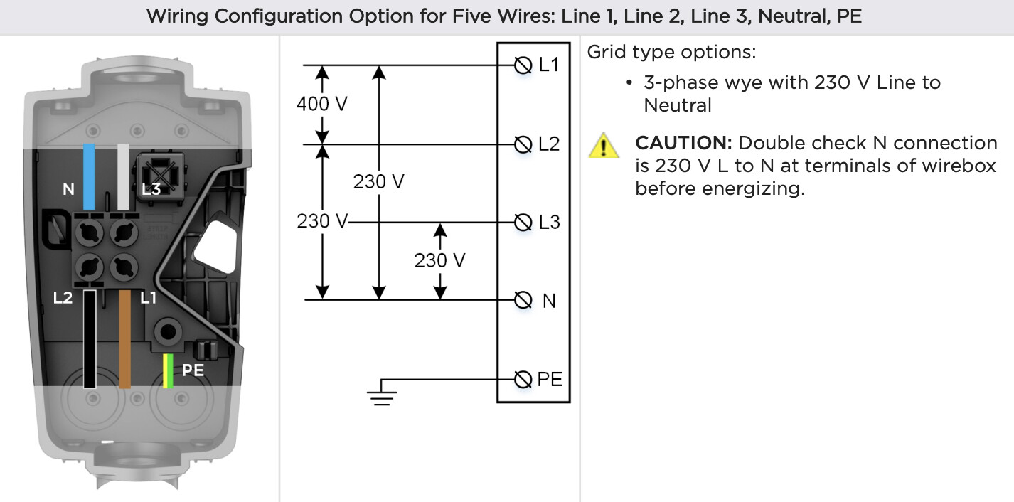
The rule is that you need one less CT than the number of wires. Let’s say you put CTs on phases A and B. You would use a voltage references of AC and BC respectively. With derived reference, IoTaWatt can derive those references. Do you have the model of the charger? The documentation may reveal whether it is Wye (4 wire), or Delta (three wire).
Looks like it does have a Neutral
Yeah that’s wye, but it says that’s an option implying there are other ways to connect. Can you send me a link and/or look for a “delta” option?
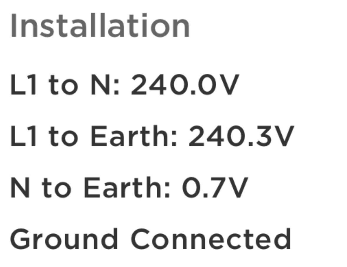
I took a screenshot of my charger’s admin interface, though im not sure if this implies it’s not using 3 phase because it definitely is.
I had a play around trying to get a formula working for a rough approximation, because it seems each phase draws almost exactly the same load during charging and I came up with the following:
Server Watts = Tesla_A - (Tesla_B min Tesla_C) max 0
Tesla Watt = ((Tesla_A + Tesla_B + Tesla_C) - (Tesla_A - (Tesla_B min Tesla_C))) max 0
I’m wondering what your thoughts are of this approach
I’d simplify it.
Server = Input 5 - Input 6
or perhaps
Server = Input 5 - ((Input 6 + Input 7) / 2)
Tesla = (Input 6 + Input 7) * 1.5
If Input 6 and 7 are zero, then you will get zero for the Tesla.
2 Likes
Should work ok, but it would be good to remove the server from the L1 CT for a day, run a Tesla charge cycle, then plot the three Tesla for that day. Compare the kWh for each to see if they are all alike. The power used to charge is probably pulled evenly from all three, but there may be extra small load on one phase for power supply, controls and maybe cooling fan(s). If there is such a phase, say it’s TeslaA you might want to add the server to one of the others, say TeslaB. Then
Server = (TeslaB - TeslaC ) max 0
Tesla = TeslaA + TeslaC + TeslaC
EDIT:
Or simplify even more by simply putting the third CT on only the server. Then:
Server = Server
Tesla = TeslaA + TeslaC + TeslaC
Thanks for your help. I think I’ll take it off the Phase A of the Tesla and put it on the server as suggested.